A fail-safe magnetic pogo pin connector is not a connector that is guaranteed never to fail. In engineering, fail-safe design means that foreseeable faults are detected, contained or directed toward a condition that does not create unacceptable damage.
A magnetic pogo pin interface may experience contamination, insufficient compression, offset mating, worn contacts, an open circuit, an unintended short circuit or a damaged cable. The connector architecture should therefore be evaluated not only under normal mating conditions, but also under realistic abnormal conditions.
The most reliable approach combines mechanical guidance, spring-loaded contacts, magnetic alignment, electrical protection, system diagnostics and defined fault-response logic.
“Fail-safe” does not mean “failure-proof.” A failure-proof claim assumes that failure cannot occur. A fail-safe design accepts that faults are possible and controls what the system does when they occur.
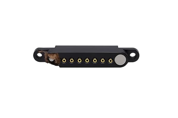
What Does Fail-Safe Mean in a Magnetic Connector?
For a magnetic pogo pin connector, fail-safe behavior normally means that an abnormal contact condition does not automatically create uncontrolled power delivery, overheating, damage to sensitive circuits or unsafe device operation.
A fail-safe architecture may be designed to:
- keep the main power output disabled until correct mating is confirmed;
- limit current during initial contact;
- detect abnormal voltage or resistance;
- disconnect power after a contact fault;
- use redundant ground or detection contacts;
- prevent incorrect orientation mechanically;
- report a connector fault to the system controller;
- allow the device to enter a defined safe state.
The connector is only one part of this architecture. Mechanical design, PCB circuitry, firmware and application-level safety requirements must be coordinated.
Fail-Safe Is Different from High Reliability
High reliability and fail-safe behavior are related, but they are not identical.
| Concept | Main objective | Example |
|---|---|---|
| Reliable design | Reduce the probability of a fault occurring. | Maintain controlled pogo pin compression and suitable contact resistance. |
| Fail-safe design | Limit the consequence when a fault occurs. | Disable the main power output when correct mating is not detected. |
| Fault-tolerant design | Continue operating after a defined fault. | A second ground contact maintains the return path after one contact becomes open. |
| Diagnostic design | Identify and report an abnormal condition. | Firmware detects abnormal voltage drop across the connector. |
A well-designed interface may use all four concepts, depending on the application risk.
Common Magnetic Pogo Pin Failure Modes
Before defining protection measures, engineers should identify how the interface could fail.
| Failure mode | Possible cause | Possible system effect |
|---|---|---|
| Open contact | Insufficient compression, contamination, damaged spring or misalignment. | Charging interruption, reset, missing signal or loss of module detection. |
| High contact resistance | Wear, oxidation, debris, low force or damaged plating. | Voltage drop, unstable operation or local temperature rise. |
| Adjacent-contact short | Offset mating, conductive debris or excessive exposed pad area. | Overcurrent, circuit damage or incorrect signal state. |
| Reverse connection | Symmetrical housing, incorrect accessory or uncontrolled pin map. | Reverse polarity or voltage applied to the wrong circuit. |
| Intermittent contact | Vibration, housing movement, uneven compression or weak retention. | Repeated resets, communication errors or unstable charging. |
| Stuck plunger | Debris, deformation, corrosion or side loading. | One circuit may fail to engage while other contacts appear normal. |
1. Define the Safe State Before Designing the Connector
A fail-safe design begins by defining what the device should do after a connector fault.
The safe state depends on the application. Examples include:
- stop charging while keeping the device operational;
- disable a removable accessory;
- reduce output power;
- save data and shut down;
- switch to an internal backup supply;
- alert the user and request maintenance;
- prevent the system from starting.
There is no universal safe state. Disconnecting power may be safe for a consumer charging accessory but inappropriate for equipment that must remain operational during a temporary connector fault.
Questions to answer
- What happens if one power contact opens?
- What happens if one ground contact opens?
- What happens if two adjacent pads are bridged?
- Can the connector be partially mated while energized?
- Should the device continue operating after a fault?
- How quickly must the fault be detected?
- Can the user safely reconnect the interface?
2. Keep Main Power Disabled Until Mating Is Confirmed
One of the most useful fail-safe methods is separating connector detection from main power delivery.
A low-energy detection contact can confirm that:
- the expected accessory is present;
- the connector is sufficiently engaged;
- the orientation is correct;
- the required ground path exists;
- the system is ready to enable the load.
The system controller can then activate a load switch, relay, MOSFET or charging circuit only after the expected detection condition is satisfied.
Ground contact engages → identification contact is detected → voltage is checked → the main power path is enabled.
This reduces the chance that a partially mated connector immediately energizes exposed or incorrectly aligned contacts.
3. Use Contact Sequencing Where the Application Requires It
Contacts do not always engage simultaneously. Their length, installed height and position can be used to create a controlled sequence.
Possible sequences include:
- ground before power;
- detection before main power;
- pre-charge before full current;
- main power disconnect before ground during separation;
- signal connection only after stable power is confirmed.
Sequencing can be created through different pogo pin lengths, different pad heights or electronic timing. Mechanical sequencing must account for dimensional tolerance and angled mating.
The sequence should be tested under:
- straight mating;
- tilted mating;
- slow connection;
- rapid connection;
- partial connection;
- contaminated contact conditions.
4. Limit Fault Current During Initial Contact
A short circuit or high inrush current can cause more damage when the power source can deliver substantial current immediately.
Possible protective measures include:
- current-limited power supplies;
- electronic fuses;
- resettable protection devices;
- load switches;
- pre-charge circuits;
- reverse-polarity protection;
- overvoltage protection;
- temperature monitoring.
The protection threshold should be coordinated with the connector, cable, PCB traces and normal load behavior. A protection device set too high may not protect the contact. A threshold set too low may trigger during normal startup.
5. Use Redundant Contacts Selectively
Redundant pogo pins can reduce dependence on a single contact, but redundancy should be applied deliberately.
Functions that may benefit from redundancy include:
- ground;
- selected power paths;
- connector detection;
- safety-related enable signals.
Parallel contacts can provide an alternative path if one contact becomes open. However, current may not divide equally between the contacts.
Current sharing is affected by:
- individual contact resistance;
- working compression;
- PCB routing;
- solder-joint resistance;
- pad condition;
- temperature.
The design should be tested with one contact intentionally open or increased in resistance. This reveals whether the remaining contacts can carry the load safely and whether the system detects the degraded condition.
6. Separate Electrical Contacts from Structural Loads
Pogo pins are designed primarily for axial compression and electrical contact. They should not carry significant shear, torsion or enclosure-alignment loads.
The connector housing should provide:
- mechanical locating surfaces;
- anti-rotation features;
- guide walls or posts;
- stops that control final compression;
- support for cable and enclosure loads.
This separation reduces the chance that side loading bends the plunger, damages the barrel or produces uneven contact force.
Fail-safe benefit
When structural loads are carried by the housing, damage to one mechanical guide is easier to detect and less likely to create an invisible electrical degradation inside a pogo pin.
7. Keep Every Contact Inside Its Working-Stroke Range
A pogo pin may appear connected even when it is operating outside the intended compression range.
The complete tolerance stack should include:
- pogo pin free and installed height;
- PCB thickness and position;
- mating-pad height;
- housing dimensions;
- magnet position;
- adhesive or overmolding thickness;
- enclosure deformation;
- thermal expansion;
- wear after repeated mating.
| Condition | Risk | Possible control |
|---|---|---|
| Under-compression | Low or unstable contact force. | Adjust installed height, housing stop or mating-pad position. |
| Over-compression | Bottoming, spring damage or PCB stress. | Add a mechanical stop and verify worst-case tolerance. |
| Uneven compression | Different resistance across the contact array. | Improve flatness, support and alignment control. |
8. Design for Detectable Degradation
Some connector failures develop gradually rather than appearing as an immediate open circuit.
Examples include:
- contact resistance slowly increasing;
- magnetic retention becoming weaker;
- one of several parallel contacts becoming inactive;
- plunger movement becoming restricted;
- cable conductors beginning to fatigue;
- contamination accumulating on the mating surface.
A diagnostic system may monitor:
- voltage drop across the connector;
- charging current versus expected current;
- connector temperature;
- repeated connection resets;
- module identification errors;
- unexpected changes in breakaway or retention behavior.
Not every product needs continuous connector monitoring. However, high-value or difficult-to-service equipment may benefit from maintenance indicators or fault logging.
9. Control Conductive Debris and Surface Contamination
Magnets can attract iron-containing particles. Moisture, oil, dust and cleaning residue can also affect the contact surface.
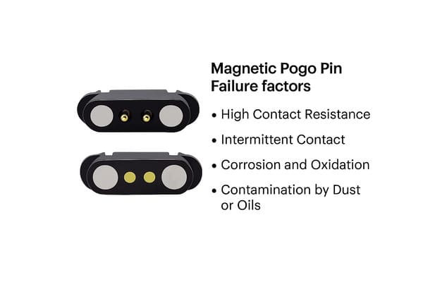
Contamination can lead to:
- adjacent-contact bridging;
- incomplete pogo pin compression;
- higher contact resistance;
- scratched plating;
- unstable magnetic spacing;
- stuck plungers.
Possible design controls include:
- recessed power contacts;
- insulating ribs between pads;
- protective covers;
- larger spacing between high-risk circuits;
- drainage and cleaning access;
- software detection before power enable;
- maintenance and inspection instructions.
10. Derate the Connector for Real Operating Conditions
Electrical ratings should not be based only on a short bench test at room temperature.
Contact resistance and temperature rise may change with:
- minimum working compression;
- elevated ambient temperature;
- repeated mating;
- surface contamination;
- cable length;
- parallel-contact imbalance;
- enclosure heat accumulation.
The usable current should be based on the complete path:
- power source;
- cable conductors;
- termination joints;
- pogo pin contacts;
- mating pads;
- PCB traces;
- protection devices.
Fail-safe design also asks what happens after resistance increases. The system may need to reduce current or shut down before the connector reaches an unacceptable temperature.
11. Apply FMEA to the Connector Interface
Failure Mode and Effects Analysis, or FMEA, provides a structured way to review connector risks before production.
A connector FMEA should consider:
- failure mode;
- cause;
- system effect;
- existing prevention controls;
- existing detection controls;
- recommended action;
- responsibility;
- verification evidence.
Example connector FMEA entries
| Failure mode | Prevention | Detection or response |
|---|---|---|
| Reverse mating | Mechanical keying and asymmetric layout. | Accessory identification before enabling power. |
| One power contact open | Controlled compression and optional redundant contact. | Voltage-drop monitoring or current reduction. |
| Adjacent contacts bridged | Contact spacing, recessed pads and insulating walls. | Current limiting and fault shutdown. |
| High resistance | Material, plating, force and contamination controls. | Temperature or voltage-drop monitoring. |
| Incorrect magnet polarity | Assembly fixture and polarity verification. | Functional mating inspection before shipment. |
12. Validate Fault Conditions, Not Only Normal Operation
A fail-safe magnetic pogo pin connector should be tested under deliberately introduced faults.
| Fault test | What to verify |
|---|---|
| One contact held open | System detects, tolerates or safely responds to the missing circuit. |
| Increased contact resistance | Voltage drop and temperature remain controlled or trigger protection. |
| Offset mating | No unsafe power or signal combination occurs. |
| Partial mating | Main power remains disabled until the required contacts are stable. |
| Conductive debris | Protection limits current and the design prevents unacceptable bridging. |
| Abnormal cable pull | Connector separates or remains retained according to the defined safe behavior. |
| Vibration with live monitoring | Intermittent contact is detected and remains within agreed criteria. |
| Protection-device failure | The system does not depend on one unverified protection layer. |
Acceptance criteria should be defined before testing. Possible criteria include:
- maximum fault current;
- maximum connector temperature;
- maximum interruption duration;
- required shutdown time;
- permitted degraded operating mode;
- required user notification;
- post-fault recovery behavior;
- no permanent damage to protected circuits.
When a Magnetic Pogo Pin Interface May Not Be Appropriate
A different connector architecture may be more suitable when:
- a standardized safety-rated connector is mandatory;
- the connection must remain mechanically locked under high force;
- the environment contains uncontrolled conductive debris;
- the system cannot tolerate exposed live contacts;
- high-speed data requires a standardized controlled-impedance interface;
- the interface remains permanently connected and does not need repeated docking;
- the device has no circuitry available for detection or fault protection.
Fail-safe engineering may therefore involve selecting a different connector rather than adding more protection to an unsuitable magnetic design.
Information Required for a Fail-Safe Connector Design
To evaluate a custom fail-safe magnetic pogo pin connector, provide:
- application and device function;
- definition of the required safe state;
- pin count and pin assignment;
- continuous and peak current;
- operating voltage;
- signal types and data rates;
- hot-plugging requirement;
- required power-up sequence;
- allowed connector fault conditions;
- retention or breakaway requirement;
- available connector dimensions;
- mating direction and possible misalignment;
- environmental and contamination conditions;
- required diagnostics or fault reporting;
- PCB, FPC, wire or cable termination;
- 2D drawings, 3D models and circuit references.
Frequently Asked Questions
Can a magnetic pogo pin connector be completely fail-proof?
No connector can be assumed immune to every possible fault. A fail-safe design identifies foreseeable failure modes and limits their consequences through mechanical, electrical and software controls.
What is the safest way to enable power through a magnetic connector?
A common approach is to detect correct mating through a low-energy contact, verify the expected condition and then enable the main power path through a controlled switch or protection circuit.
Should power and ground use redundant pogo pins?
Redundancy may be useful, but the remaining contacts must be able to carry the load safely if one contact fails. Current sharing and fault detection should be verified.
Can magnets prevent all incorrect connections?
No. Magnetic polarity can guide orientation, but mechanical keying and electrical fault protection should be used when incorrect mating could damage the device.
How can high contact resistance be detected?
Possible methods include monitoring connector voltage drop, charging current, local temperature, repeated resets or differences between expected and measured load behavior.
Does waterproofing make a connector fail-safe?
No. Environmental sealing reduces certain moisture and contamination risks. It does not address reverse mating, short circuits, overheating, cable damage or software response.
What is the role of FMEA in connector design?
FMEA helps the engineering team list foreseeable faults, evaluate their effects and define prevention, detection and response measures before production.
Conclusion
A fail-safe magnetic pogo pin connector should not be marketed as a component that eliminates every possible device failure. Its engineering value comes from controlling how the system behaves when a foreseeable contact fault occurs.
The design should define a safe state, detect correct mating before enabling power, control contact sequencing, limit fault current and prevent one contact failure from creating unacceptable system behavior. Mechanical guidance, working compression, contamination control and diagnostic logic must be evaluated together.
CTP supports custom development of magnetic pogo pin connectors, magnetic cable assemblies, pogo pin connector assemblies and individual pogo pins.
For a new fail-safe interface, submit your pin map, current, voltage, safe-state requirement, power sequence, available space and expected fault conditions through our Get a Quote & Samples page. The connector, protection circuit and fault-response strategy can then be reviewed as one system.