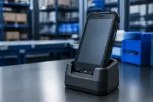
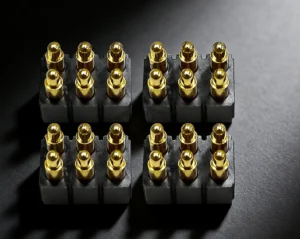
A wearable magnetic charging interface should be defined early in the
product architecture rather than added after the enclosure and PCB are
already fixed. The engineering team must decide how the user charges the
device, which side contains the spring-loaded contacts, how the charger is
mechanically oriented, what functions belong in the Pin Map, when charging
power is enabled, how heat moves through the complete current path and which
parts should be replaceable. These seven decisions determine the connector
architecture before detailed reliability validation begins.
Start with the Charging Architecture, Not the Connector
A wearable charging system is more than a pair of electrical contacts.

It normally includes:- the wearable enclosure;
- device-side electrical contacts;
- charging head, cradle or dock;
- magnets and mechanical guides;
- cable or PCB conductors;
- charger electronics;
- connection-detection logic;
- the user interaction required to attach and remove the charger.
Therefore, the first design question should not be:


    “Should we use a 2-pin or 4-pin magnetic pogo connector?”
It should be:
“What charging architecture should the product use?”
A useful design chain is:
    Wearable Product
    →
    Charging Workflow
    →
    Charger Architecture
    →
    Mechanical Interface
    →
    Pin Map
    →
    Power Architecture
    →
    Connector Geometry
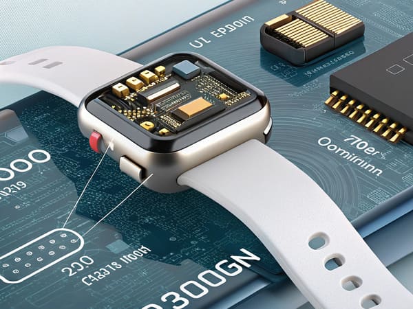
charger and enclosure architecture rather than as an isolated connector.
Decision 1: Choose the Charger Format Before Freezing the Wearable Housing
Wearable products can use several different magnetic charging
architectures.| Charger Format | Main Characteristic | Typical Design Question |
|---|---|---|
| Magnetic Cable Head | Small removable charging head attached directly to the device | How should cable pull and breakaway be managed? |
| Charging Cradle | Wearable sits inside a mechanically guided structure | How much alignment should the cradle provide? |
| Flat Charging Dock | Device rests against a fixed magnetic charging surface | How is final position controlled? |
| Clip / Clamp Charger | Mechanical structure adds positive contact compression | Is magnetic retention still necessary? |
A Cable Head and a Cradle Solve Different Problems
A small magnetic cable head places more responsibility on the magnetic
interface because the connector itself may need to provide:- capture;
- orientation;
- retention;
- breakaway behavior.
A cradle can instead use the surrounding plastic structure to provide:- gross positioning;
- rotation control;
- mechanical support;
- cable-load isolation.
In that architecture, the magnets may only assist final capture.Do Not Select the Connector Before Selecting the Charging Workflow
The same wearable may require a completely different connector geometry
depending on whether it is charged:- while being worn;
- while lying flat;
- inside a cradle;
- through a cable head;
- inside a multi-device dock.
Charger format should therefore be established before the connector
envelope is frozen.
Decision 2: Decide Which Side Should Contain the Pogo Pins
One of the most important architecture decisions is often overlooked:


    Should the spring-loaded pogo pins be located on the wearable or on the
    charger?


Both configurations are possible.
Option A: Pogo Pins on the Charger
The wearable can use relatively flat target contacts while the charging head contains the moving spring contacts.
Potential advantages include:
- a simpler device-side external surface;
- moving contact mechanisms located on a replaceable accessory;
- easier replacement if the charger-side spring contacts wear or become damaged;
- less pogo-pin body depth inside the wearable.
But engineers still need to consider:
- target-pad exposure;
- contact spacing;
- wet-state behavior;
- charger-head thickness;
- cable strain relief.
Option B: Pogo Pins on the Wearable
The device can instead contain the pogo pins while the charger provides
fixed conductive targets.

This may make sense where the product architecture or target geometry favors
the arrangement.

However, the wearable now carries:- the spring-contact body;
- associated installed-height requirements;
- more internal Z-axis package demand;
- the wear-sensitive moving contact structure.
The Decision Should Include Service Cost
For many consumer and professional wearables:


    Replaceable Charger
    =
    Relatively Low Service Cost
while:
    Device-Side Connector Failure
    =
    Product Disassembly or Device Replacement


That does not mean pogo pins must always be charger-side.

It means the location of the wear mechanism should be a deliberate
architecture decision.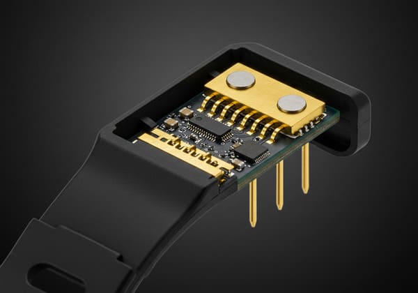
wearable or the replaceable charging accessory before finalizing the
mechanical package.
Decision 3: Separate Magnetic Capture from Mechanical Orientation
Wearable charging heads are often designed to feel as though they
automatically “find” the device.

That experience normally requires more than magnetic attraction.
A controlled mating architecture is:
    User Approach
    →
    Magnetic Capture
    →
    Mechanical Orientation
    →
    Final Datum
    →
    Contact Compression
Magnets Help the Charger Find the Interface
The magnetic system can create an attractive region that reduces the amount
of precision required from the user.

But the final position should normally be established by:- housing geometry;
- chamfers;
- locating bosses;
- asymmetric features;
- mechanical stops.
Orientation Must Be Designed Explicitly
Wearable chargers may need to prevent:- 180-degree reversal;
- offset attachment;
- incorrect accessory placement;
- partial overlap between neighboring contacts.
Orientation controls can include:- magnet polarity;
- asymmetric magnet positions;
- mechanical keying;
- asymmetric contact layout;
- system-level charger identification.
Do Not Let Magnet Force Define Working Stroke
Final mechanical stops should establish the seated position.

The pogo pin then operates at a defined compression instead of being driven
until magnetic force and spring reaction happen to reach equilibrium.
Decision 4: Build the Pin Map from the Charging System
Pin count should be the result of the charging architecture.

It should not be selected first.
A better design flow is:
    Required Functions
    →
    Pin Map
    →
    Contact Count
    →
    Contact Layout
A wearable charging Pin Map may include:
- charging power;
- power return;
- charger detection;
- accessory identification;
- diagnostic communication;
- selected control or data functions.
A Two-Pin Charger Is Architecturally Different from a Multi-Pin Interface
A basic charging pair may rely heavily on charger and device electronics to
determine whether the connection is valid.

Additional contacts can potentially provide functions such as:- presence detection;
- charger identification;
- service communication;
- additional return paths.
More contacts are not automatically better.

They also increase:- spring reaction;
- PCB routing;
- surface area;
- alignment sensitivity;
- contact-state complexity.
More Pins Do Not Automatically Mean More Data Capability
A contact being assigned to a signal does not prove that the complete
connector channel supports a particular data rate.

Signal performance can depend on:- signal-to-return allocation;
- contact geometry;
- pitch;
- PCB transition;
- cable or FPC architecture;
- complete channel length.
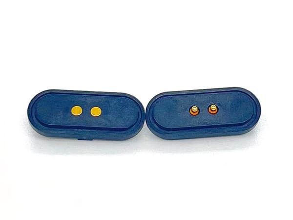
communication functions rather than being selected as an isolated
connector specification.
Decision 5: Define When Charging Power Is Allowed to Turn On
This is one of the most important system-level decisions in a wearable
magnetic charger.

Magnetic attachment begins before the connector has necessarily reached its
final seated position.

Therefore:


    Magnetic Attachment
    ≠
    Mechanical Seating
    ≠
    Valid Charging State
The Interface Can Pass Through Several States
| State | System Question |
|---|---|
| Charger Absent | What electrical state exists on exposed device contacts? |
| Initial Capture | Have any contacts begun to touch? |
| Partial Mate | Are all required power and return paths established? |
| Fully Seated | Has the charger reached the intended mechanical position? |
| Validated | Has the system confirmed the charger or connection state? |
| Charging | Is full charging power permitted? |
A Controlled Sequence Can Be Used Where Required
Depending on product architecture:


    Charger Approaches
    →
    Magnetic Capture
    →
    Mechanical Seating
    →
    Connection Detection
    →
    Charger Validation
    →
    Charging Enable


Not every wearable needs every stage.

The important principle is:


    magnetic attachment does not need to equal immediate full-power
    charging.
This Matters for Exposed Wearable Contacts
Device-side contacts may encounter:- sweat;
- water;
- cleaning residue;
- skin oils;
- foreign conductive objects.
Enclosure waterproofing and exposed-contact electrical behavior are
different requirements.

The charger architecture should define the intended electrical state while
the charger is absent, partially seated or attached to wet contacts.
Decision 6: Design the Entire Charging Current Path as One System
The current path does not begin and end at the pogo pin.A wearable charger can include:
    Power Adapter
    →
    Charging Cable
    →
    Charger PCB / Termination
    →
    Pogo Pin
    →
    Device Target
    →
    Wearable PCB
    →
    Charging IC
    →
    Battery
A simplified path resistance is:
    Rpath =
    Rcable +
    Rtermination +
    Rpogo +
    Rinterface +
    Rtarget +
    RPCB
Voltage drop follows:
Vdrop = I × Rpathand resistive loss follows:
Ploss = I² × RpathConnector Geometry and Thermal Design Are Coupled
A smaller wearable charging head may use:- smaller conductors;
- less PCB copper;
- shorter contact spacing;
- less thermal mass;
- less enclosure volume for heat spreading.
Therefore, increasing current may force changes outside the pogo pin itself.Parallel Power Contacts Need Array-Level Validation
When multiple contacts are placed in parallel, equal current sharing should
not be assumed.
Differences can result from:
- working stroke;
- contact resistance;
- target flatness;
- charger tilt;
- PCB routing;
- termination resistance.
Current capability should therefore be confirmed through complete-path
voltage-drop and temperature-rise validation.
Decision 7: Define the Charger Ecosystem and Service Boundary
The final architecture decision extends beyond the first charger shipped
with the product.

Engineers should decide whether the charging interface will support:- one dedicated cable;
- multiple charger variants;
- desktop docks;
- multi-device charging stations;
- factory test fixtures;
- service accessories;
- future generations of the wearable.
Physical Compatibility Is Not Enough
Two chargers that magnetically attach to the same wearable are not
automatically compatible.
The interface contract may need to control:
- contact geometry;
- magnetic polarity;
- mating orientation;
- Pin Map;
- voltage architecture;
- charger identification;
- allowed current;
- connection-state logic.
A Common Interface Can Become a Product Platform
If carefully controlled, one wearable-side charging interface can
potentially support:


    Charging Cable
    +
    Desktop Dock
    +
    Factory Fixture
    +
    Service Tool
    +
    Future Accessory


This can create value beyond the original connector.
Decide Which Side Should Be the Replaceable Wear Component
The charging cable or dock is often easier to replace than:- the wearable main PCB;
- the sealed rear housing;
- an internal connector module.
The contact architecture should therefore include a deliberate service
strategy.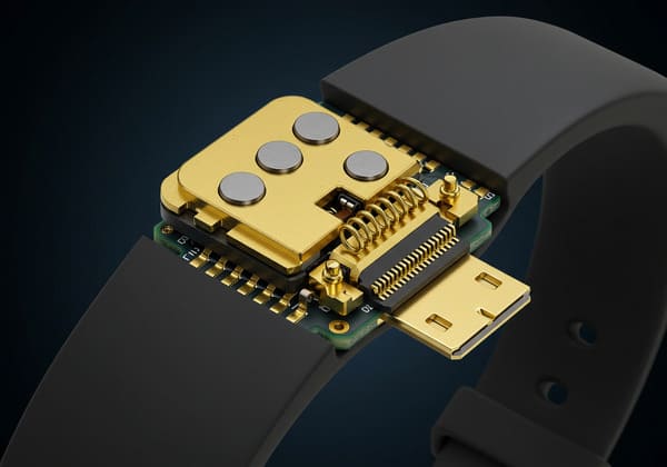
and service tools when mechanical and electrical compatibility remain
under one interface specification.
The Seven Architecture Decisions at a Glance
| Architecture Decision | Main Question |
|---|---|
| 1. Charger Format | Cable head, cradle, dock or another charging structure? |
| 2. Contact-Side Allocation | Should the pogo pins sit on the wearable or the charger? |
| 3. Mating Geometry | How are capture, orientation and final positioning separated? |
| 4. Pin Map | Which power, return, detection and communication functions are needed? |
| 5. Power Enable | When does attachment become a valid charging state? |
| 6. Current Path | Can the complete charging path meet voltage-drop and thermal requirements? |
| 7. Ecosystem & Service | Which chargers, docks and service tools should share the interface? |
The Architecture Is Coupled: Changing One Decision Can Change the Entire Connector
These seven decisions should not be optimized independently.For example:
    Add Charger Detection
    →
    Add Contact
    →
    Larger Pin Map
    →
    More Spring Reaction
    →
    Different Magnetic Retention
    →
    Different Connector Geometry
or:
    Move Pogo Pins to Charger
    →
    Flatter Wearable Surface
    →
    Different Charger Thickness
    →
    Different Cable / Dock Architecture
or:
    Increase Charging Current
    →
    Larger Conductive Path
    →
    More PCB / Cable Requirement
    →
    Different Thermal Behavior
    →
    Different Connector Package


This is why wearable charging-interface design should begin at system level.
Architecture Decisions vs Reliability Validation
After these architectural decisions are frozen, the next phase is
reliability validation.| Architecture Question | Later Reliability Question |
|---|---|
| Where are the pogo pins? | How do the contacts wear and contaminate? |
| What is the final mechanical datum? | Does working stroke remain stable across tolerance and aging? |
| What is the Pin Map? | Do voltage drop and signals remain inside limits? |
| When is power enabled? | What happens during sweat, wet mating and contamination? |
| What is the breakaway architecture? | Does retention remain acceptable over service life? |
Keeping these two stages separate prevents the design article from becoming
the same as a lifecycle or reliability article.
What Should Be Frozen Before the Wearable Housing Is Too Far Along?
Before the mechanical design becomes difficult to change, define:- charger type;
- device-side and charger-side contact architecture;
- mating direction;
- mechanical datums;
- magnetic polarity concept;
- Pin Map;
- charging voltage and current;
- connection-detection strategy;
- allowed exposed-contact power state;
- cable / dock structure;
- service strategy.
Information Required for a Wearable Charging Interface Review
| Project Input | Information to Provide |
|---|---|
| Wearable Type | Watch, band, sensor, headset, medical wearable or another device |
| Charger Format | Cable head, cradle, dock or proposed architecture |
| Available Space | X, Y and Z envelope on both charger and device sides |
| Mating Direction | Rear, side, bottom or another surface |
| Pin Map | Power, return, detection, identification and signals |
| Charging Load | Voltage, continuous current, peak current and charging duration |
| Magnetic Behavior | Capture, retention and separation requirements |
| Connection Logic | Whether detection or charger identification is required |
| Environment | Sweat, water, cleaning fluid, dust or other exposure |
| Charger Ecosystem | Cable, dock, factory fixture or future accessory requirements |
| Project Files | 2D drawing, 3D enclosure and PCB layout |
Frequently Asked Questions
How should I design a magnetic charging interface for a wearable?
Start with the charging workflow and charger format, then define which side
contains the pogo pins, mating geometry, Pin Map, power-enable logic,
complete charging path and service strategy before finalizing connector
dimensions.
Should the pogo pins be on the smartwatch or on the charger?
Either architecture is possible. The decision should consider package
depth, exposed surfaces, expected wear, service cost and which side is
easier to replace.
Should a smartwatch use a magnetic cable or a charging cradle?
A cable head provides a compact removable interface, while a cradle can use
more mechanical guidance and support. The correct choice depends on user
workflow, enclosure geometry, retention and charging environment.
How many pins does a wearable magnetic charger need?
Pin count should follow the required functions. Define power, return,
charger detection, identification and any communication paths first, then
determine the required number of contacts.
Do magnets determine the final charger position?
Magnets can assist capture, but mechanical datums, guides and stops should
normally establish final orientation and position.
Should charging begin as soon as the magnetic charger attaches?
Not necessarily. Magnetic attachment may occur before full mechanical
seating. Depending on the product, charging can be enabled only after the
required connection state has been detected or validated.
Can exposed smartwatch charging contacts remain powered?
That decision depends on voltage, spacing, environmental exposure and the
charging-system architecture. Exposed, wet and partially mated states should
be considered separately.
Can magnetic pogo pins support faster charging?
Charging capability depends on the complete conductive and thermal path,
including cable, termination, contacts, target pads, PCB and charging
electronics. Magnetic attachment alone does not increase charging power.
Can one magnetic charging interface work with several chargers?
Yes, if mechanical geometry, magnetic polarity, Pin Map, voltage, current
limits and identification logic are controlled as one interface
specification.
What is the advantage of placing pogo pins on the replaceable charger?
It can place the moving spring-contact mechanism on a lower-cost replaceable
accessory instead of inside the wearable, although the best arrangement
still depends on the complete product architecture.
Can a magnetic charger also be used for factory testing?
Potentially. A controlled interface may be reused for charging, service or
production fixtures if the electrical and mechanical interface contract
supports those functions.
What should be designed first: the wearable enclosure or the charging connector?
They should be developed together. Charger format, contact-side allocation,
mating geometry and PCB routing can directly affect the wearable enclosure
and available internal space.
Request a Wearable Charging Interface Engineering Review
Explore

    CTP custom magnetic connector solutions

for wearable charging, docking and removable product interfaces.

Review

    pogo pin and spring-contact connector solutions

for different board, cable and module architectures.

Learn more about CTP engineering and manufacturing capabilities on the

    About Us page
. Submit your wearable enclosure, charging concept, Pin Map, voltage,
current, available X-Y-Z space, desired charger format and available
2D or 3D files to CTP for an engineering review.
The device-side and charger-side interfaces can be reviewed together
before the enclosure, contact layout and charging architecture are
frozen.
Final electrical performance, thermal behavior, environmental
protection, lifecycle and magnetic behavior should be confirmed against
the approved connector revision and project-specific validation
conditions.
CTP ENGINEERING PATHS
Choose the right path for your project
Move from application requirements to a connector pair, a data-capable cable assembly, or a charging cable configuration. Final specifications are confirmed against an approved drawing and project validation plan.
Magnetic Connectors
Connector geometry, pin layout, mechanical integration and OEM/ODM review.
Engineering overview → 02Magnetic Data Cables
Power and signal allocation, cable exit, interface selection and assembly review.
Cable engineering → 03Magnetic Charging Cables
Browse the complete cable catalog and shortlist a starting structure for customization.
View cable catalog →