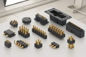
Magnetic pogo pin connectors can be well suited to wearable charging and
removable accessory interfaces because they support compact contact
surfaces, low-effort mating and spring-loaded Z-axis compliance. However,
wearable reliability is not created by magnetic attraction alone. The
interface must survive frequent user handling, dimensional variation,
charging current, sweat, skin oils, cleaning, wet exposed contacts and
repeated mating. The following seven design priorities focus specifically
on those wearable use conditions.
Wearable Connector Reliability Starts with the Real Use Profile
A smartwatch or wearable sensor does not experience the same connector
environment as an internal PCB contact or industrial docking station.

The interface is often:- small;
- externally exposed;
- connected frequently;
- handled without precise alignment;
- exposed to sweat and skin oils;
- cleaned repeatedly;
- attached to a lightweight device with limited mechanical margin.
This means the correct starting question is not:


    “How many mating cycles can this pogo pin achieve?”
It is:
    “What mechanical, electrical and environmental states will this
    wearable interface actually experience during its service life?”


A useful wearable mission profile can include:| Use Condition | Questions to Define |
|---|---|
| Charging Frequency | How often is the connector attached and removed? |
| User Interaction | One-handed, blind, angled or visually guided mating? |
| Exposure | Sweat, skin oil, water, dust, cosmetic products or cleaners? |
| Electrical Load | Voltage, continuous current, peak current and charge duration? |
| Mechanical Load | Cable pull, peel, accidental snagging or side load? |
| Service State | Mated, unmated, wet, contaminated or partially seated? |
Once this profile is defined, engineers can evaluate whether a magnetic pogo
pin architecture is appropriate and what must be controlled.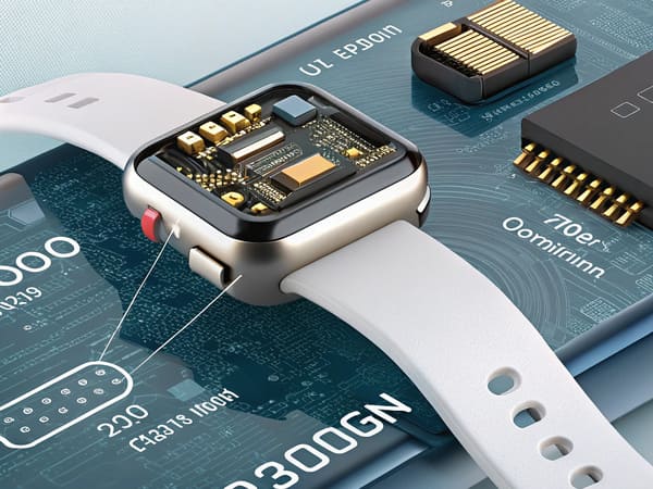
packaging, exposed contacts and environmental contamination in one
compact electromechanical boundary.
Priority 1: Use Magnetic Capture to Reduce Mating Effort—not to Define Final Position
One reason magnetic pogo pin connectors work well in wearables is that the
user can bring the charging head close to the device rather than accurately
inserting a plug into a narrow receptacle.

Magnetic attraction can assist the final approach.

However, the connector should still separate several mechanical functions:


    User Approach
    →
    Magnetic Capture
    →
    Mechanical Guidance
    →
    Final Datum
    →
    Pogo Pin Compression
Why mechanical datums still matter
The final connector position can be influenced by:- housing geometry;
- magnet position;
- contact array tolerance;
- target-pad location;
- charging-head angle;
- enclosure deformation.
Magnetic force alone should not be expected to establish a precise and
repeatable X-Y-Z location.

Mechanical features such as:- locating bosses;
- guide walls;
- chamfers;
- asymmetric geometry;
- mechanical stops;
should normally establish the final seated position.Wrong orientation should be considered
A multi-contact wearable connector should also prevent:- 180-degree reversal;
- offset contact landing;
- partial attachment;
- incorrect accessory orientation.
Magnetic polarity can contribute to orientation control, but mechanical
keying and electrical state detection may still be useful.
Priority 2: Keep Every Pogo Pin Inside Its Working-Stroke Window
Wearables are compact, which means relatively small dimensional changes can
consume a significant portion of the available pogo pin stroke.
A simplified installed compression is:
S = Hfree - Hseatedwhere:
- S = actual pogo pin compression;
- Hfree = installed free height;
- Hseated = final seated height.
The real value is determined by the complete tolerance stack.Wearable tolerance contributors can include
- PCB thickness;
- solder height;
- connector installed height;
- plastic housing tolerance;
- target-pad height;
- rear-cover thickness;
- adhesive layers;
- mechanical-stop position.
Engineers should calculate:


    Minimum Compression
    /
    Nominal Compression
    /
    Maximum Compression


and confirm that every production condition remains within the approved
working-stroke range.
Total travel is not the same as recommended working stroke
A pogo pin may physically compress farther than the intended operating
condition.

That extra movement should not automatically become the product's mechanical
stop.

The enclosure should define final position, while the pogo pin provides
controlled electrical compliance.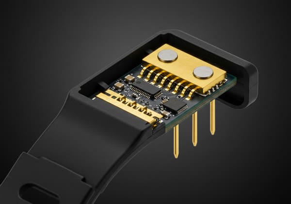
control especially important because small dimensional shifts can change
contact compression significantly.
Priority 3: Validate Charging Through the Complete Electrical and Thermal Path
A wearable charging interface should not be sized from a pogo pin current
number alone.

The complete conductive path can include:


    Charger
    →
    Cable
    →
    Connector Termination
    →
    Pogo Pin
    →
    Contact Interface
    →
    Target Pad
    →
    Device PCB
    →
    Charging Circuit
    →
    Battery
A simplified path resistance is:
    Rpath =
    Rcable +
    Rtermination +
    Rpogo +
    Rinterface +
    Rtarget +
    RPCB
Voltage drop follows:
Vdrop = I × Rpathand resistive loss follows:
Ploss = I² × RpathWhy this matters in a wearable
A compact wearable has limited space to spread heat.

Local heating can be influenced by:- contact resistance;
- PCB copper area;
- small cable conductors;
- termination resistance;
- enclosure thermal insulation;
- ambient temperature;
- charge duration.
Therefore, charging validation should include:- complete-path voltage drop;
- temperature rise;
- representative working stroke;
- real mating target;
- final cable and PCB architecture;
- post-aging performance where relevant.
Parallel contacts require current-sharing validation
If multiple contacts are placed in parallel for power or return, current
may not divide equally.
Sharing can change because of:
- stroke variation;
- contact-resistance variation;
- target flatness;
- charging-head tilt;
- PCB routing;
- termination resistance.
The complete contact array should therefore be evaluated under the real
wearable assembly condition.
Priority 4: Treat Sweat, Water and Wet Contacts as Separate Engineering Problems
Wearables frequently operate close to the skin.

Their charging contacts may be exposed to:- sweat;
- skin oils;
- water;
- soap or cleaning residue;
- cosmetic products;
- salt-containing moisture.
These exposures should not be reduced to one generic “waterproof”
requirement.
Three different requirements must be separated
    Enclosure Ingress Protection
    ≠
    Contact Corrosion Resistance
    ≠
    Safe Wet-State Electrical Behavior


A sealed wearable enclosure may prevent fluid from reaching the internal
PCB while external metal targets remain wet.
Unmated contacts may experience the most exposure
The wearable may spend most of the day without the charging cable attached.

Device-side contacts can therefore encounter contamination while:- unmated;
- powered;
- unpowered;
- wet;
- drying;
- being cleaned.
These states should be defined explicitly.Wet reconnection deserves its own fault analysis
A user may attach the charger immediately after:- exercise;
- hand washing;
- swimming;
- device cleaning.
Depending on the product, the interface can use connection detection or
controller-managed power enable so that:


    Magnetic Attachment
    ≠
    Immediate Full-Power Enable


The required strategy depends on voltage, contact spacing, fluid condition
and system architecture.
Sweat resistance should be validated against the actual exposure
A generic plating or material name does not automatically prove suitability
for prolonged skin-contact environments.

Relevant validation may include:- representative chemical exposure;
- post-exposure contact resistance;
- surface inspection;
- repeated mating after exposure;
- cleaning-cycle simulation.
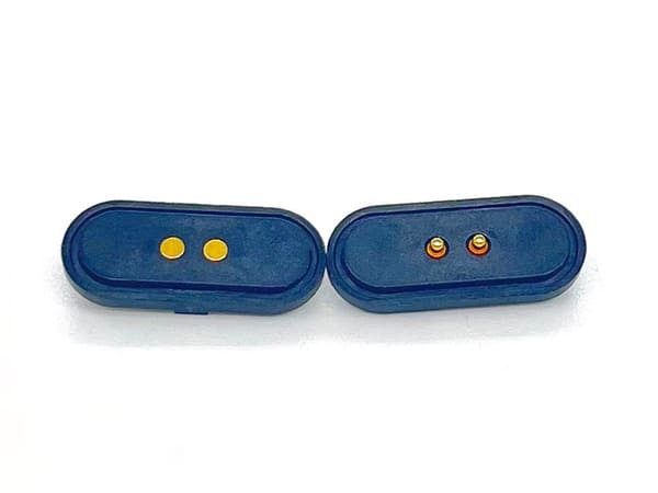
contamination and post-exposure electrical performance rather than a
dry mating-cycle test alone.
Priority 5: Tune Capture, Retention and Breakaway for Human Interaction
A wearable magnetic connector is often small enough that the user can feel
every aspect of the mating event.

Magnetic behavior should therefore be designed as part of the user
interaction.
Three requirements should be separated:
| Mechanical Requirement | Wearable Design Question |
|---|---|
| Capture | How close must the cable be before it begins to attach? |
| Retention | What normal handling loads must the connection tolerate? |
| Breakaway | At what load and direction should the charging head release? |
More magnetic force is not automatically better
Excessive attraction can create:- uncomfortable removal force;
- higher closing impact;
- more enclosure stress;
- lateral sliding during attachment;
- greater metallic-debris attraction.
Too little retention can allow accidental separation.

The correct force depends on the complete wearable geometry and user
interaction.
Axial pull and peel can behave differently
A charging head pulled straight away from the device may require a
different force than one peeled from an edge.

Cable orientation should therefore be included in breakaway testing.
Priority 6: Miniaturize the Complete Interface—not Just the Pogo Pin
Wearables create strong pressure to reduce connector size.

A shallow magnetic contact surface can reduce the need for a deep external
receptacle, but the complete connector still occupies three-dimensional
space.
The total package can include:
- pogo pin body;
- working stroke;
- magnets;
- housing;
- mechanical guides;
- PCB routing;
- FPC or cable termination;
- sealing structure;
- target pads.
Reducing Z height can increase X-Y complexity
A low-profile design may require more surface area for:- magnets;
- larger target pads;
- ground contacts;
- routing escape;
- mechanical guidance.
Therefore:


    Low connector height does not automatically mean minimum total package
    volume.
Pitch reduction creates new trade-offs
Smaller pitch can affect:- PCB routing;
- contact landing tolerance;
- electrical spacing;
- manufacturing variation;
- signal interaction;
- cleaning access.
Wearable miniaturization should therefore optimize the complete interface,
not only the distance between contacts.
Priority 7: Validate the Wearable Mission Profile, Not a Perfect Laboratory Cycle
A long dry mating-cycle test can provide useful wear information.

But it does not reproduce the complete wearable use condition.

A more representative lifecycle plan can combine:- repeated mating;
- minimum and maximum working stroke;
- angular misalignment;
- sweat or representative contamination;
- cleaning cycles;
- charging current;
- cable pull and peel;
- temperature exposure.
Define failure before testing begins
“Still works” is not a sufficient end-of-life criterion.Possible acceptance metrics include:
| Performance Area | Possible Acceptance Criterion |
|---|---|
| Contact Resistance | Project-defined maximum or drift |
| Voltage Drop | System-level maximum |
| Temperature Rise | Approved thermal limit |
| Working Stroke | Remaining inside the approved operating window |
| Retention | Project-defined force range |
| Surface Condition | No unacceptable corrosion or wear |
| Mating | Complete seating under allowed tolerance |
Post-aging charging tests are especially useful
A wearable interface may show acceptable electrical performance when new
but different behavior after:- contact wear;
- surface contamination;
- sweat exposure;
- cleaning;
- repeated mechanical loading.
Therefore, voltage-drop and temperature-rise checks after aging can provide
more useful information than initial resistance alone.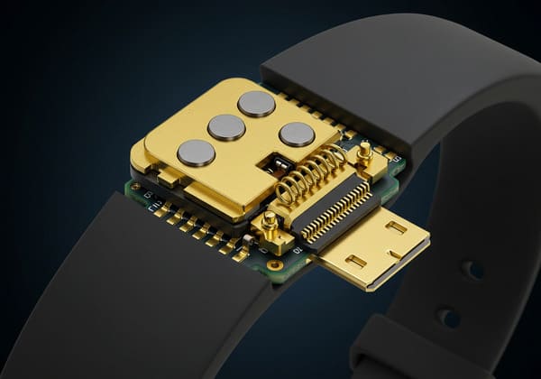
representative contamination, charging and post-aging electrical
measurements.
Seven Wearable Reliability Priorities at a Glance
| Design Priority | Main Reliability Question |
|---|---|
| 1. Capture & Alignment | Can the user attach the charger easily while mechanical geometry defines final position? |
| 2. Working Stroke | Do all production tolerances keep every pogo pin inside its operating window? |
| 3. Power & Thermal Path | Are voltage drop and temperature rise acceptable through the complete charging path? |
| 4. Sweat & Wet Contacts | What happens while contacts are wet, contaminated, unmated or reconnected? |
| 5. Breakaway | Does retention support normal use without creating excessive removal force? |
| 6. Miniaturization | Does the complete 3D interface fit without creating routing or tolerance problems? |
| 7. Lifecycle Validation | Does the test reproduce actual wearable use rather than only dry mating cycles? |
Common Wearable Connector Failure Chains
Wearable failures often result from several variables interacting rather
than one isolated defect.
For example:
    Sweat Exposure
    +
    Surface Residue
    +
    Repeated Mating
    →
    Contact Resistance Drift
or:
    Minimum Working Stroke
    +
    Housing Tolerance
    +
    Charging-Head Tilt
    →
    Reduced Contact Margin
or:
    Contact Aging
    +
    Higher Path Resistance
    +
    Charging Current
    →
    Increased Temperature Rise
or:
    Wet Contacts
    +
    Immediate Reconnection
    +
    Full Power Enable
    →
    Higher Electrical Risk


This is why wearable connector reliability should be evaluated at system
level rather than from one component specification.
What About Data Through the Wearable Connector?
Some wearable interfaces carry only charging power.

Others may also include:- device detection;
- identification;
- diagnostic communication;
- selected data signals.
A custom Pin Map can support these functions, but pin count alone does not
establish data capability.
Signal performance can depend on:
- signal-to-return allocation;
- contact geometry;
- pitch;
- PCB transitions;
- cable or FPC structure;
- complete channel length.
High-speed capability should therefore be validated for the actual channel
rather than inferred from the number of pogo pins.
Manufacturing Considerations for Wearable Magnetic Connectors
A successful prototype does not automatically prove that the connector can
be reproduced consistently at volume.
Production CTQs may include:
- contact pitch;
- installed height;
- working stroke;
- magnet polarity;
- target-pad position;
- defined electrical measurement;
- housing geometry;
- termination characteristics.
SMT compatibility should be verified—not assumed
Some pogo contacts or connector modules may be supplied in tape-and-reel
packaging.

That alone does not establish compatibility with the OEM's SMT process.
Surface-mount integration can require review of:
- pick-up surface;
- nozzle access;
- PCB pad geometry;
- coplanarity;
- reflow compatibility;
- solder paste volume;
- post-reflow installed height.
When Magnetic Pogo Pins May Not Be the Best Wearable Interface
A magnetic connector is not automatically the best choice for every
wearable.
Another architecture may be preferable when:
- standardized USB compatibility is required;
- the connection must remain positively locked;
- the product requires a standard third-party cable ecosystem;
- the magnetic package consumes too much available surface area;
- nearby magnetic-sensitive components create unacceptable constraints;
- the charging interface is rarely used;
- the added magnetic system provides little user or service value.
The correct interface should follow the complete wearable product
architecture rather than a preference for magnetic charging.
Information Required for a Wearable Magnetic Connector Review
| Project Input | Information to Provide |
|---|---|
| Wearable Type | Watch, band, sensor, headset, medical wearable or another device |
| Interface Function | Charging, detection, diagnostics, data or accessory connection |
| Available Space | X, Y and Z connector envelope |
| Mating Method | Blind, one-handed, guided or cradle-based |
| Working Stroke | Minimum, nominal and maximum compression |
| Pin Map | Power, return, detection, identification and signals |
| Charging Load | Voltage, continuous current, peak current and charge duration |
| Magnetic Behavior | Capture, retention and breakaway requirements |
| Exposure | Sweat, water, skin oils, cleaning fluid, dust or cosmetics |
| Wet-State Requirement | Expected behavior when contacts are wet or freshly cleaned |
| Lifecycle | Expected charging and cleaning frequency |
| Termination | PCB, FPC, wire or cable structure |
| Project Files | 2D drawing, 3D assembly, PCB layout and enclosure reference |
Frequently Asked Questions
Why are magnetic pogo pin connectors used in wearables?
They can support compact charging surfaces, low-effort attachment and
spring-loaded Z-axis compliance. Their actual reliability still depends on
mechanical positioning, working stroke, electrical loading and environmental
validation.
Are magnetic pogo pin connectors more reliable for smartwatches?
Not automatically. Reliability depends on the complete charging interface,
including mating geometry, contact compression, sweat exposure, target
surfaces, charging current and lifecycle conditions.
Do magnets automatically align a smartwatch charger?
Magnets can assist capture, but mechanical features should normally define
final connector position and contact compression.
What is the correct pogo pin working stroke for a wearable?
There is no universal value. It should be selected from the pogo pin design
and the complete PCB, housing, target and mechanical-stop tolerance stack.
Can sweat damage wearable charging contacts?
Sweat and residue can influence exposed contact surfaces depending on
materials, electrical state, exposure time and cleaning conditions.
Wearable-specific environmental testing should reproduce the expected use
profile.
Are magnetic wearable charging connectors waterproof?
Not automatically. A magnetic interface can be integrated into a sealed
wearable, but ingress protection depends on the complete enclosure,
feedthrough, housing joint and termination design.
Can a wearable be charged while the contacts are wet?
That depends on voltage, spacing, fluid contamination and system
architecture. Wet reconnection should be treated as a separate operating or
fault state where it can occur.
Do stronger magnets make a wearable charger more reliable?
Not necessarily. Higher attraction can increase retention but also increase
removal force, closing impact, enclosure load and metallic-debris
attraction.
Can magnetic pogo pins carry data in wearables?
Selected data or diagnostic signals can be included, but signal capability
depends on Pin Map, contact geometry, return paths, PCB transitions and the
complete electrical channel.
How should wearable magnetic connector life be tested?
The test should reflect the real mission profile, including repeated mating,
working-stroke extremes, contamination, sweat or cleaning exposure,
charging load and post-aging electrical measurements.
Are magnetic pogo pins suitable for wearable mass production?
They can be, provided the connector architecture can be transferred into
controlled production CTQs such as installed height, contact position,
working stroke, magnet polarity and electrical acceptance limits.
When should a wearable use another connector architecture?
Another connector may be better when standardized interoperability,
positive locking, third-party cable compatibility or magnetic-sensitive
product constraints dominate the design.
Request a Wearable Magnetic Connector Engineering Review
Explore

    CTP custom magnetic connector solutions

for wearable charging, removable docking and compact product interfaces.

Review

    pogo pin and spring-contact connector solutions

for project-specific contact layouts and mounting structures.

Learn more about CTP engineering and manufacturing capabilities on the

    About Us page
. Submit your connector envelope, Pin Map, working stroke, charging
voltage and current, magnetic requirements, sweat and water exposure,
expected charging frequency and available 2D or 3D files to CTP for an
engineering review.
The interface can be reviewed as a complete wearable charging boundary,
including user mating, mechanical positioning, electrical loading,
exposed-contact behavior and lifecycle conditions.
Final current capability, thermal performance, environmental
protection, magnetic behavior and service life should be confirmed
against the approved connector revision and project-specific validation
conditions.
CTP ENGINEERING PATHS
Choose the right path for your project
Move from application requirements to a connector pair, a data-capable cable assembly, or a charging cable configuration. Final specifications are confirmed against an approved drawing and project validation plan.
Magnetic Connectors
Connector geometry, pin layout, mechanical integration and OEM/ODM review.
Engineering overview → 02Magnetic Data Cables
Power and signal allocation, cable exit, interface selection and assembly review.
Cable engineering → 03Magnetic Charging Cables
Browse the complete cable catalog and shortlist a starting structure for customization.
View cable catalog →