Magnetic pogo pin connectors can create value beyond the electrical contact
itself. When the interface is designed correctly, magnetic capture,
spring-loaded compliance, custom Pin Maps and modular construction can
influence product architecture, assembly, field service and future platform
development. These benefits are not automatic properties of every magnetic
connector. Each one depends on a corresponding mechanical, electrical or
manufacturing control.
Why Magnetic Pogo Pin Connectors Should Be Evaluated Across the Hardware Lifecycle
A connector is often selected as a component near the end of a hardware
design.

For a removable interface, that can be too late.

The connector can influence:- how the user attaches a cable or module;
- how much dimensional variation the product can tolerate;
- which electrical functions cross the interface;
- how the enclosure is constructed;
- how subassemblies are manufactured;
- which part becomes the field-service item;
- whether one interface can be reused across future products.
Magnetic pogo pin connectors are therefore most useful when they are
evaluated as a product boundary, not simply as a group of
spring-loaded pins surrounded by magnets.
A useful architecture is:
    PRODUCT A
    →
    Electrical / Mechanical Boundary
    →
    PRODUCT B


The magnetic connector sits at that boundary and must simultaneously manage:- mechanical approach;
- final seating;
- electrical contact;
- retention or release;
- environmental exposure;
- service access.
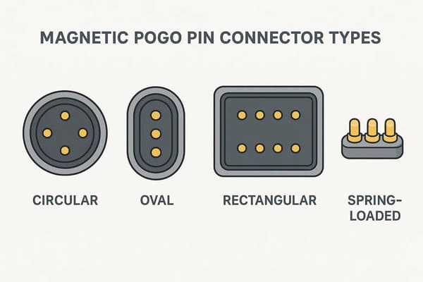
module-level, cable-side or docking interfaces depending on the product
architecture.
Three Layers of Value in a Magnetic Pogo Pin Interface
The nine benefits become easier to understand when they are grouped into
three layers.| Lifecycle Layer | System Benefits |
|---|---|
| Product Interaction | Blind mating, Z-axis compliance, controlled separation |
| System Architecture | Flexible Pin Map, connection-state control, external-surface freedom |
| Product Lifecycle | Module integration, serviceability, platform reuse |
This is important because a magnetic connector rarely creates business
value from only one feature.

Its strongest value often comes from several interface functions working
together.
Layer 1: Improving How the Product Mates and Moves
Benefit 1: Magnetic Capture Can Reduce Mating Effort
A conventional plug often requires the user or machine to position the plug
relative to a defined receptacle opening before insertion.

A magnetic interface can reduce the accuracy required during the final
approach by creating an attractive capture region around the mating
location.

This can be useful for:- one-handed charging;
- blind mating;
- automatic docking;
- removable accessories;
- equipment where the connector is difficult to see.
However:


    Magnetic capture should reduce alignment effort; it should not be relied
    on to define final precision position.
A better mating sequence is:
    Approach
    →
    Magnetic Capture
    →
    Mechanical Guidance
    →
    Final Datum
    →
    Pogo Pin Compression
Design controls required
- housing guides;
- chamfers;
- mechanical datums;
- anti-rotation features;
- target-pad size;
- allowable X-Y and angular offset.
For multi-pin connectors, mechanical or electrical keying is particularly
important because the connector must not only attach—it must attach in the
correct orientation.
Benefit 2: Pogo Pins Provide Controlled Z-Axis Compliance
One of the most useful characteristics of a spring-loaded connector is the
ability to accommodate controlled variation along the contact axis.
A simplified relationship is:
S = Hfree - Hseatedwhere:
- S = actual compression;
- Hfree = installed free height;
- Hseated = installed height after final seating.
In production, that value is influenced by more than the pogo pin itself.The tolerance stack can include:
- PCB thickness;
- solder height;
- connector housing tolerance;
- pogo pin free-height variation;
- mating-target height;
- module flatness;
- mechanical-stop position.
This compliance can reduce sensitivity to a closely fixed contact height,
but it does not eliminate the need to calculate the complete tolerance
stack.
Engineers should verify
    Minimum Compression
    →
    Nominal Compression
    →
    Maximum Compression


All three states should remain inside the approved working-stroke window.
Benefit 3: Retention and Separation Can Become Part of the Product Experience
Magnetic connectors allow the attachment force to be designed differently
from a permanent latch or threaded connector.

Three mechanical requirements should be separated:| Requirement | Engineering Question |
|---|---|
| Capture | How should the connector behave while approaching? |
| Retention | What loads must the seated interface tolerate? |
| Breakaway | When and how should the interface release? |
This allows a product team to deliberately design an interface that stays
connected under normal use but releases before a larger load is transferred
into the enclosure or cable system.

That does not mean magnetic connectors provide “zero-force breakaway.”

Separation force still depends on:- magnet arrangement;
- pull direction;
- peel angle;
- pogo spring reaction;
- cable load;
- housing geometry.
Stronger magnetic force is therefore not automatically better.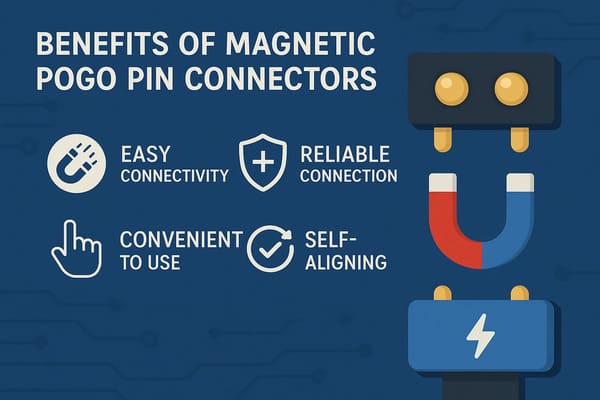
different mechanical functions and should be designed separately.
Layer 2: Expanding the Electrical and Product Architecture
Benefit 4: A Custom Pin Map Can Combine Multiple Interface Functions
Magnetic pogo pin connectors are not limited to two charging contacts.

A custom Pin Map can allocate contacts for:- power;
- power return;
- connection detection;
- module identification;
- control signals;
- selected data paths.
The correct engineering flow is:


    Product Functions
    →
    Electrical Requirements
    →
    Pin Map
    →
    Required Contact Count
    →
    Connector Geometry


This is stronger than choosing “4-pin,” “8-pin” or “12-pin” first and
then attempting to assign product functions afterward.
Power contacts require complete-path validation
A simplified conductive path is:
    Source
    →
    PCB / Cable
    →
    Termination
    →
    Pogo Pin
    →
    Contact Interface
    →
    Target
    →
    Load
Voltage drop follows:
Vdrop = I × Rpathand resistive loss follows:
Ploss = I² × Rpath

The connector current capability therefore depends on the complete path,
not simply the pogo pin diameter.
Signal contacts require channel validation
Pin count alone does not establish:- USB compatibility;
- Ethernet capability;
- a specific data rate;
- controlled impedance.
Signal performance can depend on:- signal-to-return allocation;
- contact spacing;
- PCB launches;
- reference-path continuity;
- FPC or cable construction;
- crosstalk;
- complete channel length.
Benefit 5: The Interface Can Support Connection-State Awareness
Magnetic capture begins before the connector necessarily reaches its final
seated position.

This creates a useful but important system distinction:


    Magnetic Attachment
    ≠
    Mechanical Seating
    ≠
    Valid Electrical Connection


In products where partial mating matters, the interface architecture can
include dedicated detection or identification contacts.
A possible sequence is:
    Connector Approaches
    →
    Magnetic Capture
    →
    Mechanical Seating
    →
    Connection Detection
    →
    Module Identification
    →
    Signal Validation
    →
    Main Power Enable


Not every application requires this sequence.

The advantage is that a custom pogo Pin Map allows the product designer to
build connector state into the system architecture when needed.
This is particularly useful when engineers must manage
- partial mating;
- wet exposed contacts;
- wrong accessory connection;
- module identification;
- power sequencing;
- automatic docking.
A make-first or pilot contact can provide state information, but it does not
suppress electrical arcing by itself. The controller or power architecture
must use the signal appropriately.
Benefit 6: A Shallow External Interface Can Create More Enclosure Freedom
Some plug-and-receptacle connectors require:- a deep receptacle cavity;
- an insertion path;
- shell geometry;
- clearance around the plug;
- retention hardware.
A pogo pin and flat target interface can sometimes be integrated into a
shallower exterior surface.

This can provide industrial-design advantages for products where external
depth or cavity geometry is constrained.

However:


    Flush does not mean waterproof.
The complete environmental boundary may still include:
- pogo pin feedthroughs;
- connector housing;
- device-housing joint;
- gaskets;
- potting;
- mating-target installation;
- PCB, FPC or cable termination.
A specific ingress-protection rating should only be associated with a
defined and tested assembly.
The unmated state is also important
Once the cable or module is removed, exposed contacts may encounter:- water;
- sweat;
- dust;
- cleaning fluid;
- metallic debris;
- foreign conductive objects.
Product sealing and exposed-contact electrical behavior should therefore be
reviewed separately.
Layer 3: Creating Value During Manufacturing and Field Service
Benefit 7: The Interface Can Be Supplied as an Integrated Subassembly
A magnetic pogo pin solution does not have to be supplied as separate
contacts and magnets for the OEM to assemble individually.
A connector module can combine:
- pogo pins;
- magnets;
- plastic or metal housing;
- mating target;
- PCB or FPC;
- wires;
- cable termination.
This can move interface alignment and selected assembly operations into one
controlled subassembly.

For the OEM, the potential manufacturing value is:


    Multiple Loose Components
    ↓
    Controlled Connector Module
    ↓
    Fewer Final Assembly Interfaces


This is only an advantage when the connector-module CTQs are clearly
defined.
Possible CTQs include
| CTQ Area | Possible Control |
|---|---|
| Contact Position | Pitch, installed height and coplanarity |
| Spring Interface | Working stroke and force at defined compression |
| Magnetic System | Polarity, orientation and defined retention behavior |
| Mating Target | Geometry, flatness and position |
| Electrical | Defined resistance or voltage-drop measurement |
| Termination | PCB, FPC, wire or cable requirements |
Benefit 8: Wear and Service Can Be Deliberately Assigned to a Replaceable Part
One of the less obvious advantages of a removable contact architecture is
that the engineer can decide which side should be easier to replace.

Consider a product where:- the main PCB is expensive;
- opening the enclosure is difficult;
- the external cable is inexpensive;
- the product experiences frequent connections.
The interface can sometimes be designed so that a replaceable:- cable head;
- target plate;
- contact module;
- docking subassembly;
absorbs more of the expected field wear.This creates a deliberate service architecture:
    Wear Event
    →
    Replaceable Interface Component
    ↓
    instead of
    ↓
    Main Device Disassembly


It does not make the connector wear-free.

The pogo tip, target, housing and magnetic interface can still degrade.
The advantage is that the product designer can choose where that wear is
most economical and practical to service.
Benefit 9: One Interface Can Become a Product-Platform Standard
For B2B hardware companies building multiple related products, the biggest
long-term benefit may not be the connector itself.

It may be the ability to reuse a controlled interface across:- multiple device SKUs;
- charging docks;
- service fixtures;
- removable accessories;
- future product generations.
A shared connector can create a common physical and electrical boundary
across a product family.

But compatibility requires more than matching magnetic geometry.
The platform interface must control:
- mechanical geometry;
- mating orientation;
- Pin Map;
- voltage architecture;
- power limits;
- signal logic;
- module identification;
- environmental requirements.
Two accessories that physically attach to the same connector are not
automatically electrically compatible.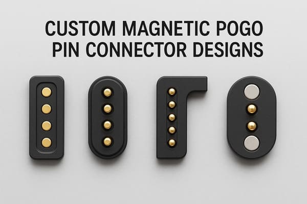
only when mechanical geometry, Pin Map, voltage and system logic remain
compatible.
The Nine Benefits and Their Required Engineering Controls
| System Benefit | Required Engineering Control |
|---|---|
| 1. Easier Mating | Mechanical guides, keying and final datums |
| 2. Z-Axis Compliance | Working-stroke and tolerance-stack analysis |
| 3. Controlled Breakaway | Capture, retention and separation-force definition |
| 4. Flexible Pin Map | Power-path and signal-channel validation |
| 5. Connection-State Control | Detection, identification and power sequencing where required |
| 6. Shallow External Interface | Complete enclosure and environmental-boundary review |
| 7. Modular Manufacturing | Connector-module CTQs and production controls |
| 8. Serviceability | Defined wear component and replacement strategy |
| 9. Platform Reuse | Controlled mechanical and electrical interface contract |
The engineering principle is:


    System Benefit
    +
    Required Control
    =
    Useful Product Function


Without the corresponding control, the same feature can become a new source
of failure.
These Benefits Are Most Valuable When They Work Together
The strongest magnetic pogo pin applications rarely rely on only one
benefit.
For example:
    Blind Mating
    +
    Controlled Z Compliance
    +
    Connection Detection
    =
    More Robust Automatic Docking Architecture
or:
    Flat External Surface
    +
    Replaceable Cable Side
    +
    Controlled Breakaway
    =
    Serviceable Portable Product Interface
or:
    Common Mechanical Geometry
    +
    Controlled Pin Map
    +
    Module Identification
    =
    Reusable Product Platform


This system-level combination is more important than simply asking whether
the connector has magnets.
When Magnetic Pogo Pin Connectors May Not Be the Right Choice
These benefits do not make magnetic pogo pin connectors universally better
than conventional connectors.
A different connector architecture may be more appropriate when:
- a permanent positive mechanical lock is required;
- the connection is made once and rarely serviced;
- standardized third-party interoperability is essential;
- very high contact density dominates the design;
- an established high-speed connector already meets the system need;
- magnetic fields create unacceptable product constraints;
- ferromagnetic contamination is difficult to control;
- the magnetic interface provides little product-level value.
Connector selection should therefore begin from the complete hardware
architecture rather than from a preference for one connector technology.
A Practical B2B Hardware Interface Decision Flow
Before selecting a magnetic pogo pin connector, ask:


    Must the Interface Be Removable?
    ↓
    Does the User or Machine Benefit from Easier Mating?
    ↓
    Is Controlled Z Compliance Valuable?
    ↓
    Is Breakaway Behavior Useful?
    ↓
    Do Multiple Electrical Functions Cross the Boundary?
    ↓
    Is Connection-State Detection Needed?
    ↓
    Does the External Surface Benefit from a Shallow Interface?
    ↓
    Should One Side Be Easily Serviceable?
    ↓
    Could the Interface Be Reused Across a Product Platform?
    ↓
    Evaluate Magnetic Pogo Architecture
Information Required Before Starting a Custom Magnetic Connector Design
| Project Input | Information to Provide |
|---|---|
| Product Boundary | Which two assemblies need to connect? |
| Available Space | X, Y and Z connector envelope |
| Pin Map | Power, return, detection, identification and signal functions |
| Electrical Load | Voltage, continuous current, peak current and duty cycle |
| Signal Requirement | Required control or communication channel |
| Working Stroke | Minimum, nominal and maximum compression |
| Mating Tolerance | X-Y-Z and angular variation |
| Magnetic Behavior | Capture, retention and separation requirements |
| Environment | Temperature, moisture, sweat, salt, dust, oil or chemicals |
| Lifecycle | Expected mating profile and service requirement |
| Service Strategy | Which interface component should be replaceable? |
| Platform Strategy | Will future products or accessories reuse this interface? |
| Project Files | 2D drawing, 3D assembly, PCB layout or enclosure model |
Frequently Asked Questions
What are the main benefits of magnetic pogo pin connectors?
Their system-level benefits can include easier mating, controlled Z-axis
compliance, tunable breakaway, flexible Pin Maps, connection-state control,
shallow external geometry, modular assembly, serviceability and product-
platform reuse.
Are magnetic pogo pin connectors more reliable than traditional connectors?
Not automatically. Reliability depends on the complete interface design,
working stroke, target geometry, mechanical positioning, electrical load,
environment and validation conditions.
Do magnets provide precise connector alignment?
Magnets can assist capture, but mechanical datums, guides and stops should
normally establish the final connector position.
What is the advantage of pogo pin working stroke?
Working stroke provides controlled compliance along the spring axis and can
absorb part of the product's Z-axis dimensional variation. The complete
tolerance stack must still remain inside the approved operating window.
Can magnetic pogo pin connectors provide breakaway protection?
They can be designed to separate under a defined load, but actual behavior
depends on magnet layout, spring reaction, pull direction, cable load and
product geometry.
Can one magnetic pogo pin connector carry power and signals?
Yes, a custom Pin Map can allocate contacts for power, return, detection,
identification and selected signals. Current and signal capability still
require project-specific electrical validation.
Does more pogo pins mean higher data bandwidth?
No. Pin count alone does not determine data performance. Contact geometry,
return paths, PCB transitions, cable construction and the complete channel
determine whether a signal requirement can be supported.
Can magnetic pogo pin connectors detect whether a module is connected?
A custom interface can include dedicated detection or identification
contacts. The system controller must then interpret those signals and
manage the required power or functional state.
Are magnetic pogo pin connectors waterproof?
Not automatically. A magnetic pogo pin connector can be integrated into a
sealed product, but the final ingress protection depends on the complete
feedthrough, housing, seal and termination architecture.
Do magnetic pogo pin connectors eliminate contact wear?
No. Spring contacts and mating targets still experience wear and can be
affected by contamination, misalignment, side load and repeated mating.
Can magnetic pogo pin connectors make a product easier to service?
They can when the interface architecture places expected wear on a
replaceable cable, target or contact module instead of an expensive
device-side assembly.
Can one magnetic connector be reused across multiple products?
Yes, but true platform compatibility requires controlled mechanical
geometry, Pin Map, voltage, power limits, identification logic and
environmental requirements.
Request a Magnetic Pogo Pin Interface Engineering Review
Explore

    CTP custom magnetic connector solutions

for removable charging, docking and modular hardware interfaces.

Review

    pogo pin and spring-contact connector solutions

for project-specific contact structures and mounting requirements.

Learn more about CTP engineering and manufacturing capabilities on the

    About Us page
. Submit your connector envelope, Pin Map, working stroke, voltage,
current, mating tolerance, magnetic behavior, environmental conditions,
service strategy and available 2D or 3D files to CTP for an engineering
review.
The interface can be reviewed not only as a connector component, but as
the mechanical, electrical and service boundary between two product
assemblies.
Final electrical performance, magnetic behavior, environmental
protection, lifecycle and production capability should be confirmed
against the approved connector revision and project-specific validation
conditions.
CTP ENGINEERING PATHS
Choose the right path for your project
Move from application requirements to a connector pair, a data-capable cable assembly, or a charging cable configuration. Final specifications are confirmed against an approved drawing and project validation plan.
Magnetic Connectors
Connector geometry, pin layout, mechanical integration and OEM/ODM review.
Engineering overview → 02Magnetic Data Cables
Power and signal allocation, cable exit, interface selection and assembly review.
Cable engineering → 03Magnetic Charging Cables
Browse the complete cable catalog and shortlist a starting structure for customization.
View cable catalog →