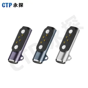
Two quotations can show a very similar magnetic head and still cover different products. One may supply the mating connector components. The other may include the cable, molded transitions, wiring and opposite-end termination. Before comparing prices or samples, make sure the item being supplied matches the work your own team intends to do.
Magnetic connector vs magnetic cable assembly is a supply-scope decision. CTP manufactures both magnetic mating components and finished cable assemblies for custom device projects. A component gives an OEM more control over its own harness and integration. A finished assembly lets the magnetic end, cable construction and remote termination be developed as one supplied connection.
A magnetic connector purchase starts at the mating interface
When your team already has a cable or board assembly route, the main requirement may be the connector itself. The drawing can then focus on the mating halves, contact allocation, mounting and the way your own production connects the part to the rest of the device.
A round component pair keeps the supply boundary compact
The CTP round male/female connector pair, CTP-RMC-0041, uses a central spring-loaded contact and a circular magnetic mating structure. It is an example of a component interface to review when a compact round connection suits the device.
The complete circuit still needs to be explained. A one-contact product description does not define the return path or every conductive feature in an assembled device. If the interface is used for power, show that whole path in the schematic before deciding what the connector supplier and your own assembly team will provide.
A four-contact linear pair can sit directly in the enclosure plan
Our four-contact single-row connector pair, CTP-MPC-4P-SR-28-A01, combines a spring-contact side, flat target side and magnetic structures beside the contact area. The linear arrangement gives the mechanical team a different proportion from the round pair.
For an OEM building a dock on its own PCB, that can be the useful level of supply. The product team defines how the receiver mounts and how its assigned contacts connect to the board. The connector geometry, dimensional references and termination should be settled in the approved drawing rather than inferred from the name.
A magnetic cable assembly includes the path beyond the head
A finished cable needs more definition than the visible magnetic interface. Its conductor arrangement, length, cable exit, molded transitions and remote-end connection all contribute to how it fits and performs in the product. Buying those elements together gives the project a single assembly definition to review.
An inline four-contact cable gives both mating halves a cable route
The CTP round inline data cable, CTP-MCC-4P-RD-A01, has two cable-terminated circular mating halves and four assigned contact positions. It suits a different integration idea from a receiver that terminates directly on a device PCB.
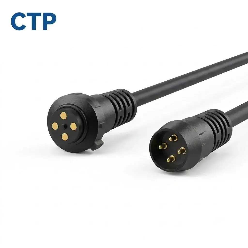
For a removable accessory between two wired sections, that inline break can be useful. The actual communication function must be supported by the complete electrical channel. Four contacts and a round shell do not establish shielding, a particular protocol or an interchangeable connection with another brand.
A molded opposite end can finish a project-specific lead
Our two-contact cable with molded termination, CTP-MCC-2P-MT-DATA-01, combines a compact magnetic end with a molded remote termination. Its contact allocation, cable length, conductor choice and device-side mating interface are defined for the project.
This is a useful supply route for an accessory brand that wants an approved complete lead rather than loose connector components. It also makes the opposite end part of the early design discussion. The required connection does not have to be squeezed into a cable that was chosen only for its magnetic head.
Match the supplier’s work to your own assembly capability
| Your production route | Supply scope to define | Details to settle together |
|---|---|---|
| You assemble the harness or device PCB | Magnetic connector components | Mating halves, mounting, termination and contact assignment |
| You buy a complete detachable lead | Finished magnetic cable assembly | Both ends, wire construction, length, cable exits and validation |
A manufacturer with its own harness team may prefer the component route so it can keep an established internal process. A smaller device brand launching a custom accessory may prefer the finished cable route so the head, lead and termination arrive as a defined assembly. Neither route removes the need for clear acceptance requirements.
Industry suppliers also distinguish these scopes; Rosenberger discusses PCB connector alternatives to cable assemblies for its own product family. The useful general point is that the mounting and termination route changes the item being supplied.
CTP can keep the connector and cable decisions in the same conversation
Our manufacturing portfolio covers magnetic connectors, magnetic cables and supporting spring-contact assemblies. That means a project can begin with the interface requirement and then settle the appropriate supply boundary, rather than forcing every device into a finished cable or a loose component purchase.
For the round inline cable, for example, identify whether the order includes both wired halves or one replacement half of an already approved pair. For the four-contact component set, identify the spring side and target side separately. This keeps a sample request from becoming a photograph of one attractive head with the rest of the connection left unspecified. It also helps your receiving team recognise exactly which parts should arrive together when the assembly is supplied.
Our custom connector RFQ article shows how that product definition can become a clearer request for samples and supply.
Show what your team will assemble and what should arrive finished. Add the mating parts, circuit allocation, enclosure space and required ends. Our OEM and ODM development information explains that project route. With the supply boundary clear, the sample and quotation can represent the connection you actually intend to buy.