
01
Pin Map and Contact FunctionsDefine the function of each power, return, signal, control or detection contact.
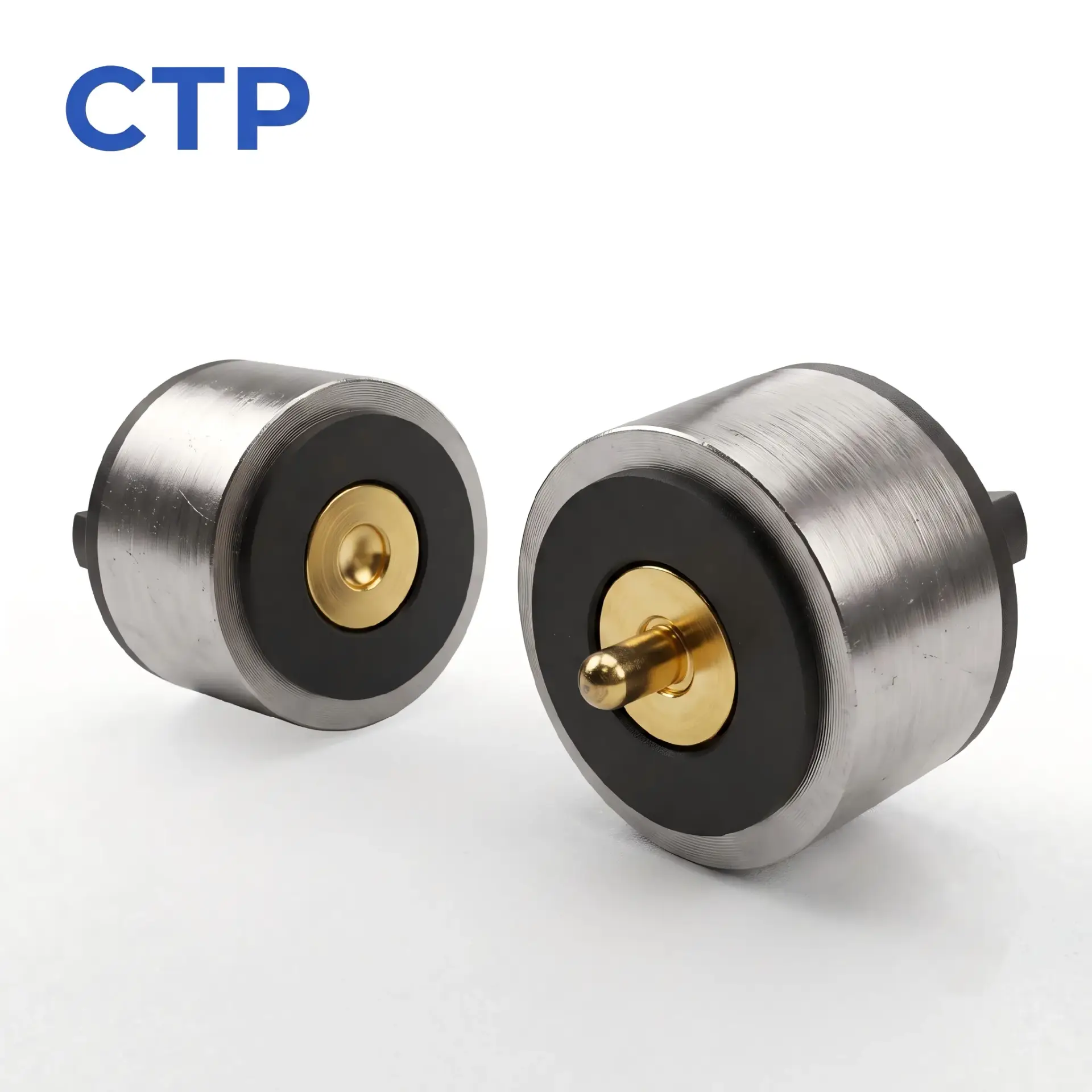
| SKU / inquiry reference | CTP-RMC-0041 |
|---|---|
| Contact count / series | 1 |
These are the pictured configuration and existing catalog references, not newly measured test results. Customer-specific dimensions, electrical ratings, sealing and reliability targets remain subject to the approved drawing and validation conditions.
SKU: CTP-RMC-0041
Values shown describe this product configuration. Customized dimensions, electrical ratings, materials and acceptance criteria are subject to the customer-approved drawing and agreed specification.
Request a drawing for SKU CTP-RMC-0041
Browse the reference drawing library — library drawings are reference structures, not approved drawings for this SKU.
CTP-RMC-0041 is a custom round 1-pin male and female magnetic power connector designed for compact low-voltage devices. It uses a spring-loaded center contact and a magnet-assisted circular mating structure to support quick, detachable connection without a conventional locking plug. Connector dimensions, magnetic force, working stroke, wire termination and enclosure integration can be customized according to the application.
Product specifications should be reviewed together with the customer device, PCB, electrical assignment and mechanical mating conditions.
Define the function of each power, return, signal, control or detection contact.
Provide voltage, continuous current, peak current and required signal conditions.
Provide available length, width, height, PCB area and required mating orientation.
Provide application, expected quantity, environment and customer validation requirements.
Review the product-specific description, technical parameters, contact arrangement, mechanical structure and project conditions below.
Engineering Summary: CTP-RMC-0041 is a round male and female magnetic power connector for custom low-voltage DC interfaces. It combines a magnetic mating structure with spring-loaded electrical contacts and can be integrated into a PCB, cable, wire harness, or application-specific connector module.
A round magnetic power connector should be specified as a complete male-and-female interface rather than as an individual pogo pin or magnet. Electrical performance depends on both connector halves, the pogo pin working stroke, mating-pad condition, termination method, magnetic air gap, and the final device installation.
CTP-RMC-0041 is intended for projects requiring a compact and detachable power connection where a conventional friction-fit plug or locking connector is not the preferred user interface.
The CTP-RMC-0041 is a circular magnetic connector pair consisting of a spring-loaded contact side and a corresponding mating side. Magnets assist the two parts during approach and help retain the connector after mating. The compressed pogo pin or spring-loaded contact provides the local electrical contact pressure.
The connector system performs three separate functions:
| Function | Primary Structure | Engineering Purpose |
|---|---|---|
| Electrical contact | Spring-loaded contact and mating target | Completes the DC power path |
| Connector attraction | Magnet system | Assists approach and retains the connector halves |
| Final positioning | Housing geometry and mechanical stop | Controls alignment and pogo pin compression |
Magnets should not be used as the only method of controlling final position. The housing and mechanical stop should define the seated geometry and the actual pogo pin working stroke.
The following values describe the current reference configuration. Final product ratings should be confirmed in the approved CTP drawing and through application-specific validation.
| Specification | Reference Configuration |
|---|---|
| CTP Product Reference | CTP-RMC-0041 |
| Product Type | Round male and female magnetic power connector |
| Electrical Function | Low-voltage DC power transmission |
| Reference Rated Voltage | DC 12V |
| Reference Rated Current | 2A for the complete mated system |
| Reference Magnetic Force | 3N under the defined assembled condition |
| Reference Contact Resistance | ≤50mΩ under the defined working stroke and measurement method |
| Reference Pogo Pin Force | 80±20gf at 1.1mm working stroke |
| Reference Mechanical Operation | a model-specific cycle-life target validated under defined test conditions under the approved test conditions |
| Magnetic Material | NdFeB or project-approved equivalent |
| Supply Scope | Male and female connector pair |
| Termination | Configured according to PCB, wire, cable or module requirements |
| Ingress Protection | Determined by the final enclosure and sealing structure |
Engineering Note: Current, voltage, resistance, magnetic force and mechanical-life values apply only to the approved connector construction and test conditions. They should not be transferred to a modified cable, PCB, housing or enclosure without review.
A circular connector envelope can be useful when the available installation area is round, centrally located or constrained by a cylindrical device housing.
The final installation should still define:
The magnetic structure can assist the user or mechanical assembly during connector approach. It can reduce the need for a conventional threaded, latched or friction-fit mating action.
The capture force, seated holding force and cable-peel release force should be treated as separate mechanical requirements. One general magnetic-force value does not fully describe connector behavior.
The spring-loaded contact compensates for a defined amount of axial dimensional variation. Stable electrical contact depends on maintaining the pogo pin inside its approved working-stroke range.
The mechanical tolerance review should include:
A magnetic connector can create a controlled separation point between a cable, device or removable module. The release behavior depends on the direction of force and should be tested in the final installation.
The connector should be evaluated as one part of the complete power path:
Before approving the connector, define:
Where several contacts are connected in parallel, current sharing should be measured rather than assumed. Differences in working stroke, contact resistance and PCB routing may cause one channel to carry more current than another.
The magnets, pogo pin springs, housing and device enclosure form one mechanical system.
Review the following before prototype approval:
Stronger magnets are not automatically better. Excessive attraction may increase mating impact, pogo pin compression, housing load, or user removal force.
The connector can be reviewed for several supply structures:
| Integration Option | Suitable Project Condition | Primary Engineering Check |
|---|---|---|
| PCB-mounted connector | The connector is installed directly onto the device PCB | Footprint, soldering, PCB support and working height |
| Wire-terminated connector | The connector connects to an internal wire harness | Wire gauge, soldering or welding and strain relief |
| Magnetic cable assembly | The customer requires a finished detachable cable | Cable conductors, opposite-end connector and overmolding |
| Integrated magnetic module | The connector is supplied with housing, PCB, cable or sealing structure | Complete dimensional, thermal and environmental validation |
The CTP-RMC-0041 architecture may be considered for low-voltage products requiring a detachable round power interface, including:
Application suitability should be confirmed based on the product voltage, current, environment, mating frequency, enclosure, and cable-loading requirements.
Custom development may include:
| Requirement | Recommended Evaluation |
|---|---|
| Electrical path | Contact resistance, voltage drop and temperature rise |
| Working stroke | Minimum, nominal and maximum assembly conditions |
| Magnetic behavior | Capture, holding and separation force in defined directions |
| Repeated operation | Project-defined mating cycles with pre- and post-test measurements |
| Cable durability | Pull, flexing and strain-relief evaluation |
| Environment | Application-specific temperature, humidity, contamination or chemical exposure |
| Final enclosure | Complete device-level sealing and functional validation |
Provide the following information for an engineering review:
The reference configuration is a complete male and female magnetic connector pair. The final supply scope should be confirmed in the quotation and approved drawing.
The current reference configuration is intended for DC 12V and 2A operation. Final ratings depend on the complete contact path, working stroke, termination, cable or PCB conductors and allowable temperature rise.
The complete connector must be rated as one mated system. A higher rating for one individual half does not increase the approved current of the complete interface.
Magnetic behavior can be adjusted through the magnet dimensions, arrangement, material, air gap and magnetic return structure. Holding and release forces should be defined separately.
Waterproof performance depends on the complete connector insert, enclosure, cable entry, seals, adhesive and tested mating state. The magnetic connector alone should not be assigned a universal IP rating.
Yes. The connector may be reviewed as an individual component, a wire-terminated assembly, a complete magnetic cable, or an integrated module.
The reference product is positioned as a power connector. Data capability requires a suitable Pin Map, return path, contact layout, cable construction, and channel-level validation.
Provide a 2D or STEP drawing, available installation space, voltage and current, Pin Map, mating direction, cable requirement, and expected operating environment.
Review related round and circular magnetic connectors, access the connector engineering guides, or submit your electrical and mechanical requirements through the Get Quote & Samples page.
CTP can review the connector geometry, Pin Map, electrical path, pogo pin working stroke, magnetic structure, PCB or cable termination and enclosure integration before prototype development. Final parameters should be confirmed in the approved project drawing and validation plan.
This product page presents a CTP magnetic connector configuration for engineering reference. Final dimensions, electrical ratings, materials, magnet structure, sealing level and reliability targets are not universal values; they are confirmed against the approved drawing, installation condition and model-specific validation plan.
CTP reviews the application and prepares a drawing or specification for approval before sample production. Test scope, acceptance criteria and report format should identify the model, sample status, method, conditions, result and review date.
Yes. Customization can cover geometry, contact layout, materials, cable construction, magnetic structure, sealing and appearance. Feasibility depends on the application and approved specification.
No. Current, voltage, resistance, temperature rise and ingress-protection claims apply only to the identified model and stated test conditions.
Timing is confirmed after the drawing, materials, tooling, sample quantity, validation scope and production requirements have been reviewed.
ENGINEERING CONFIRMATION BEFORE SAMPLING
Confirm power, signal and grounding allocation for the intended device.
Confirm working stroke, alignment, mounting, retention and mating behavior.
Confirm cable exit, host interface and project-specific assembly requirements.
Use the approved drawing and agreed validation plan as the release reference.
Submit your Pin Map, electrical requirements, available space, mating structure and project quantity for connector selection or custom development review.

Use the following engineering guides to compare contact count, contact allocation and connector layout before confirming the final product or customized design.
Review the complete selection path from contact count and electrical functions to connector shape.
View Main Guide →Compare one-contact special structures, complete two-contact circuits and third-contact functions.
Compare Low-Pin Designs →Determine whether four contacts are sufficient or whether a defined fifth electrical path is required.
Compare 4 Pin and 5 Pin →Calculate the contact budget and compare six-contact, multi-row and customized contact-array structures.
Compare High-Pin Designs →