A moving contact is not always a pogo pin. Some interfaces use a guided plunger inside a barrel; others use a formed metal beam that flexes against the mating surface. Both can create a spring connection, but they ask different things of the available space and the way the parts meet.
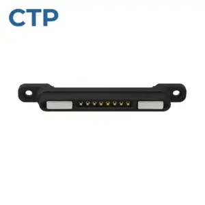
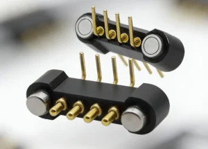
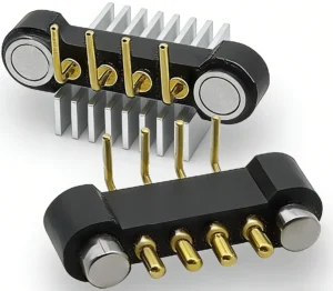
A pogo pin vs leaf spring contact comparison should start with that movement. Pogo pins provide guided travel along the plunger axis. A leaf spring develops force as its formed metal geometry bends. CTP’s individual pins and housed pogo connector assemblies give a device designer several ways to use the plunger approach, with straight, flanged and right-angle mounting structures.
Pogo pin travel and leaf spring deflection need different space
In a pogo pin, the plunger moves within its body and is loaded by an internal spring. In a formed leaf contact, the metal beam itself supplies the spring action. The beam therefore needs its intended deflection space, while the pogo pin needs room for its body and specified installed compression.
Neither is automatically the more durable or electrically capable choice. Those results depend on the selected contact, mating surface, finish, movement and operating conditions. Harwin’s spring-contact introduction shows both plunger-based contacts and formed spring styles, illustrating why their physical design should be considered separately.
A flanged pogo pin gives the installation a distinct body feature
Our flanged spring-loaded pin, CTP-PP-A0X, has a stepped cylindrical body with a visible shoulder. It is worth considering where the surrounding product needs a different body profile from a plain cylinder.
The flange’s actual locating or retaining role must be defined in the part drawing. Its useful feature is the available geometry: the designer has a shoulder to compare with the support and housing while the plunger meets its target along the contact axis.
A long DIP body provides a straight route into a PCB
The CTP DIP spring-loaded pin, CTP-PP-DIP-A01, uses a long cylindrical body and a straight through-hole-style mounting tail. It offers a different installation route when the contact should extend from a board toward a defined mating target.
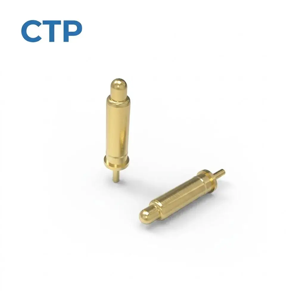
For a removable board meeting targets above the main PCB, an individual pin can let the contact locations follow the available space. The board support should establish the final seated distance. The spring contact can then operate within its defined travel rather than act as the mechanical stop for the assembly.
A leaf spring contact can be attractive when a formed beam fits the surface
A formed contact may fit a shallow space where its beam can deflect as intended. Depending on its design, it may provide a contact action suited to a flat surface, grounding point or other compact interface. Its available deflection and the approach of the mating part deserve the same care as a pogo pin’s installed position.
If the device’s shape gives the beam a suitable working area, a leaf-contact route may be appropriate. If the designer instead needs guided axial travel from a defined cylindrical body, a pogo pin may make the mechanical relationship easier to develop. Comparing those shapes early is more useful than selecting one technology from a general claim about quality.
The target surface helps make that comparison practical. A pogo pin needs a landing area that remains beneath its tip as the parts reach their seated position. A formed beam needs the target to meet the intended part of its contact geometry without trapping the beam against the housing. For a narrow target strip, look at the full approach movement as well as the final position. This is where our individual DIP pin offers layout freedom: its location can follow a particular target. A housed row offers the opposite benefit, coordinating several contact locations in one assembly where the target pattern is already defined.
Housed pogo connectors bring several moving contacts into one layout
A five-contact right-angle row changes the mating direction
Our five-contact right-angle pogo connector, CTP-PC-5P-SR-A01, uses a single row and bent PCB tails. It is a product option where the contact interface and the board termination need to operate in different directions.
For a side-facing accessory pocket, that can be a useful alternative to arranging several individual straight pins around the edge of the board. The integrated housing keeps the row coordinated. The product’s guides still need to locate the accessory without dragging it across the plungers in an unintended direction.
Our six-contact through-hole row, CTP-PC-6P-SR-A01, offers a one-by-six arrangement with straight PCB tails. It can suit a different board and target relationship where a straight mounting route matches the product.
Imagine a small control module whose target strip runs along its underside. A straight six-contact row may fit that strip naturally. A module entering from the side may lead the team toward the right-angle five-contact format instead. The useful advantage is having distinct mounting architectures to compare against the actual movement.
Choose the contact motion before refining the connector outline
As a spring-contact and connector manufacturer, CTP can review the body, housing and termination around the device’s available space. An individual pin gives layout freedom; a housed connector coordinates several positions. Both remain part of an assembly whose mating targets and installed position need to be defined.
Our pogo pin types guide gives more context on the mounting choices. Bring the direction in which the parts approach, the target area and the space available behind it. Once the movement is clear, it becomes much easier to decide whether a guided plunger or a flexing beam belongs in that connection.