A low contact-resistance figure is useful only when everyone knows what was measured. One report may cover the mating contact alone. Another may include the PCB joint and a length of wire. The numbers can look different without describing a different quality of connector.
Magnetic connector contact resistance measurement should therefore define the electrical path, seated position and test method before samples are compared. At CTP, the connector layout and project drawing give that discussion a concrete starting point. Two-contact interfaces, single-row families, sealed dual-row pairs and board-mounted contact blocks each create a different physical route to the measuring points.
Define the magnetic contact path before comparing resistance
The first question is simple: where do the measurement leads connect? If the intention is to assess a mating contact, including a long lead wire changes the meaning of the result. If the intention is to approve a finished assembly, excluding its terminations may leave out the very parts the buyer needs to evaluate.
Low-resistance work commonly uses a four-wire, or Kelvin, arrangement. Separate leads carry the test current and sense voltage close to the defined terminals, reducing the effect of lead resistance. Keysight explains that measurement principle. The appropriate current, instrument range and acceptance criteria still need to match the connector and project specification.
A two-contact magnetic interface makes the circuit paths easy to name
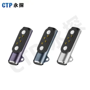
Our two-contact magnetic pogo connector, CTP-MPC-2P-CT-A01, uses two independent spring-loaded contacts in a compact mating structure. Where the circuit assigns these to supply and return, the two paths can be identified separately in the drawing and measurement plan.
For a small charging accessory, that clarity helps distinguish a contact reading from a complete supply-and-return loop reading. The housing’s seated position also needs to be reproduced, so the test does not evaluate an arbitrary amount of plunger compression.
A single-row connector family still needs a specific sample definition
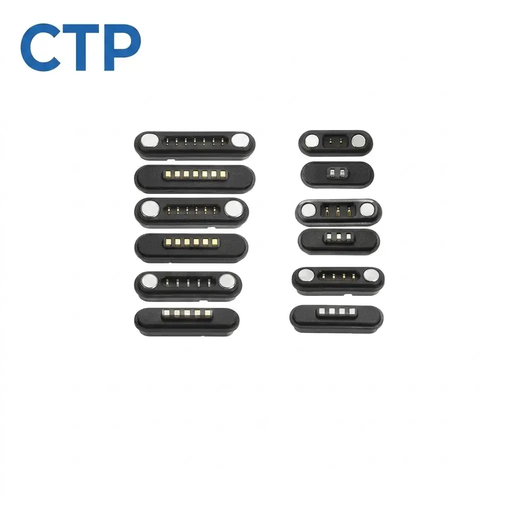
The CTP two-to-seven-contact magnetic series, CTP-MPC-2-7P-SR-SERIES, provides several single-row contact configurations. This is useful for a device family that needs different contact counts while exploring a similar general connection style.
Each contact count brings its own housing and assigned functions
A two-contact sample should not stand in for every member of a seven-contact interface. The contact layout, housing length and circuit allocation can change. Identify the actual configuration under review and the path being measured, rather than assigning a general result to the entire family.
For example, an OEM may be developing a basic dock and a version with additional control functions. Both can use a linear magnetic interface, but the supplier review should keep their drawings and sample results separate. Our range offers those layout choices without making them electrically interchangeable by appearance.
A dual-row magnetic pair needs a repeatable seated condition
The sealed dual-row structure includes more than the visible contact row
Our two-to-eight-contact dual-row magnetic series, CTP-MPC-2-8P-DR-WP-SERIES, combines paired interfaces, a spring-contact side, a target side and a perimeter sealing structure. It gives the mechanical team another route where two rows fit the available space.
The intended seating should be established with the housing and any specified sealing arrangement in place. Pressing a loose sample by hand can create a condition the finished device never reaches. A useful comparison records the selected mating pair and installed relationship, not just the instrument display.
For a compact enclosure, this helps connect the electrical review to the packaging decision. The contact arrangement may suit the device well, but the product’s stops and support still need to let the interface reach its defined working position. The final ingress-protection result also depends on the complete validated assembly.
It is also worth agreeing how samples are remated between readings. If the two-contact pair is separated and reconnected for each reading, record that action; if the dual-row specimen stays closed throughout, record that instead. Neither method should be hidden behind a single average. For an OEM reviewing several samples, retain the individual specimen identities and the relevant contact positions. This lets an unexpected result be traced to the selected housing, contact path or seating condition. The benefit of defining those details with CTP is practical: the sample under review remains connected to the configuration you intend to order, rather than becoming an anonymous connector on a test bench.
A board-mounted contact block creates a different measurement boundary
The CTP ten-contact through-hole block, CTP-PC-10P-DR-A02, uses a five-by-two contact arrangement with straight PCB tails. It has no magnetic mating mechanism; the surrounding product or fixture establishes the position of its mating targets.
That makes it a useful option to compare when the device already has its own guides and retention. For resistance assessment, decide whether the board joints belong inside the measured path. A connector mounted on a sample PCB and a loose contact block can otherwise produce results with different boundaries.
| Result description | Information that makes it useful |
|---|---|
| Mating-contact resistance | Defined terminals, matching target and installed contact position |
| Connector-and-board path | Included joints, PCB reference points and specimen configuration |
| Complete wired interface | Included wire length, terminations and named electrical path |
CTP’s project and validation support is built around defined drawings, sample configurations and acceptance requirements. That is more useful to a purchasing team than an impressive number detached from the product being supplied.
Where the seated contact position needs further review, our pogo pin force-displacement explanation connects spring movement with the installed interface.
When reviewing samples, ask for the measured path to be marked on the same drawing used to identify the part. Then compare results taken under the agreed conditions. You can make a better connector decision when the figure describes the connection your device will actually use.