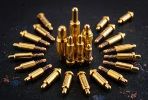
Standard and magnetic pogo pin connectors share the same basic
spring-contact principle. The key difference is not the electrical contact
itself, but how the complete interface is captured, positioned and retained.
A standard pogo pin connector normally relies on the surrounding product,
fixture, housing or latch for retention, while a magnetic connector adds a
magnet-assisted capture and holding system. The correct architecture
depends on mating workflow, mechanical datums, working stroke, dynamic
loading, partial-mate behavior, environment, packaging, serviceability and
cost.
Start with the Similarity: Both Architectures Use Spring-Loaded Contacts
The phrase “standard pogo pin connector versus magnetic pogo pin connector”
can make the two technologies sound more different than they really are.

In both cases, the electrical interface is typically based on a
spring-loaded contact system.
A pogo pin commonly performs two functions:
- provides an electrical contact path;
- provides controlled axial compliance through spring movement.
The magnetic system does not replace the pogo pin.

Instead, it adds another mechanical function around the contact system.
A useful distinction is:
    STANDARD POGO INTERFACE
    =
    Pogo Contacts
    +
    External Mechanical Retention / Positioning
while:
    MAGNETIC POGO INTERFACE
    =
    Pogo Contacts
    +
    Magnetic Capture / Retention
    +
    Mechanical Positioning


This distinction changes the product architecture, even though the
spring-contact principle remains similar.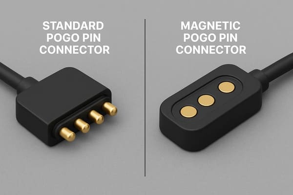
electrical contacts while relying on different mating and retention
architectures.
The Real Design Question: Who Holds the Interface Together?
Before comparing the seven differences, engineers should first identify
which part of the product is responsible for keeping the pogo pins
compressed against their mating targets.
Possible retention methods include:
- product enclosure geometry;
- screws;
- snap fits;
- latches;
- hinges;
- spring-loaded fixtures;
- robotic docking hardware;
- permanent magnets.
Therefore, a “standard” pogo pin connector is not necessarily loose or
difficult to align.

For example, an internal battery contact can be held in permanent
compression by the enclosure, while a production fixture can guide a pogo
array into position using precision mechanical datums.

The magnetic version becomes useful when the connector itself should
participate in capture, retention or breakaway.
Difference 1: Retention Architecture
Standard Pogo Pin Connector
In a standard pogo pin architecture, the pogo spring supplies contact force,
but another mechanical structure normally keeps the two assemblies together.
This structure might be:
- a housing;
- a latch;
- a compression fixture;
- a product cover;
- a screw or fastener;
- another module-retention mechanism.
This can be an excellent solution when the product already needs a positive
mechanical lock.
Magnetic Pogo Pin Connector
A magnetic design adds magnetic attraction as part of the retention system.

It can reduce the need for:- a user-operated latch;
- a threaded connection;
- a separate cable lock;
- another dedicated attachment mechanism.
However, magnetic retention should still be evaluated against all forces
acting on the interface.
A simplified force-budget concept is:
    Available Retention
    >
    Pogo Spring Reaction
    +
    Cable / Module Load
    +
    Seal Reaction
    +
    Expected Dynamic Disturbance


The exact margin depends on the application.
Engineering decision
If the product already provides secure mechanical retention, adding magnets
may create little additional value.

If easy removable attachment is part of the user or machine interaction,
magnetic retention may justify the added system complexity.
Difference 2: Capture and Final Alignment
One of the biggest misconceptions is that standard pogo pin connectors
always require precise manual alignment while magnetic connectors
automatically create perfect alignment.

Neither statement is universally true.
Standard interfaces can also support blind mating
A non-magnetic pogo pin system can use:- guide pins;
- chamfers;
- locating walls;
- fixture datums;
- tapered housings;
- robotic alignment.
These mechanical structures can provide highly repeatable alignment.Magnets can reduce the capture burden
The primary advantage of a magnetic interface is that attraction can help
draw the two assemblies into the intended mating region during the final
approach.
A useful magnetic mating sequence is:
    Approach
    →
    Magnetic Capture
    →
    Mechanical Guidance
    →
    Final Datum
    →
    Pogo Compression


The final position should still normally be established by mechanical
features.

Magnets can help the connector find the interface.


    Mechanical datums should define where the connector finally stops.
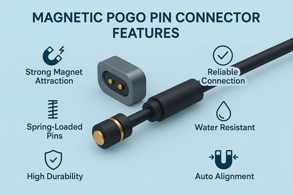
should normally establish the final connector position and pogo pin
compression.
Difference 3: Mating Workflow and User Interaction
The two architectures can produce very different product experiences even
when the electrical contacts are nearly identical.
Standard pogo pin interface
The mating workflow may be:
    Align Product
    →
    Engage Mechanical Structure
    →
    Compress Pogo Pins
    →
    Lock / Hold Assembly


In many internal or fixture-based applications, the user may never interact
directly with the pogo pins at all.
Magnetic pogo pin interface
The workflow can become:
    Bring Interfaces Close
    →
    Magnetic Capture
    →
    Mechanical Seating
    →
    Electrical Contact


This can be useful where the connection must be:- frequently removable;
- one-handed;
- difficult to see;
- automatically docked;
- easy for a user to reconnect.
Magnetic does not mean “zero effort”
The connector still has measurable:- capture force;
- retention force;
- axial separation force;
- peel behavior;
- closing impact.
These should be tuned to the product rather than assumed to be universally
better.
Difference 4: Working Stroke and Mechanical Tolerance
Adding magnets does not remove the basic pogo pin requirement for controlled
working stroke.

Both standard and magnetic architectures need an installed compression
window.
A simplified relationship is:
S = Hfree - Hseatedwhere:
- S = actual pogo compression;
- Hfree = installed free height;
- Hseated = final seated height.
The complete tolerance stack can include:- PCB thickness;
- solder height;
- pogo pin free height;
- housing dimensions;
- target height;
- module flatness;
- mechanical-stop variation.
What changes with magnets?
In a magnetic connector, the retention system must also work against the
total spring reaction created by the compressed pogo pins.

If several contacts are used:


    Total Spring Reaction
    ≈
    Sum of Individual Contact Reactions


This relationship becomes part of the magnetic force budget.
Mechanical stops remain important
The final working stroke should not simply depend on “how hard the magnets
pull.”

A controlled stop or datum should establish final position.

Otherwise, housing deformation, spring variation or seal compression can
change the installed condition.
Difference 5: Dynamic Loads and Connection Stability
Magnetic connectors are often described as automatically more resistant to
vibration.

That conclusion is too simple.
Standard pogo pin connector
If the interface is held by a rigid fixture, screwed housing or positive
mechanical lock, its dynamic behavior can be highly stable.
Magnetic pogo pin connector
Magnetic retention can help maintain assembly engagement where a removable
connector would otherwise require another retention mechanism.

But electrical continuity still depends on:- working stroke;
- contact force;
- mechanical movement;
- target geometry;
- side loading;
- vibration direction;
- retention margin.
Therefore:


    The connector remaining physically attached does not automatically
    prove uninterrupted electrical contact.
Dynamic validation should monitor the circuit
When contact interruption matters, the test should define:- mechanical excitation;
- electrical load;
- monitoring bandwidth;
- allowed interruption duration;
- pass/fail criteria.
The correct architecture is the one that passes the actual system
requirement—not automatically the one containing magnets.
Difference 6: Partial Mating and Connection-State Behavior
Both standard and magnetic pogo pin connectors can experience incomplete
mating.

However, the transition is particularly important in magnetic interfaces
because electrical contacts can begin approaching each other while the
magnetic system is already pulling the assemblies together.
Possible states include:
- fully separated;
- magnetically captured but not seated;
- one edge seated first;
- only some pogo pins compressed;
- fully seated;
- beginning separation.
These are different mechanical and electrical states.A useful distinction is:
    Magnetic Capture
    ≠
    Mechanical Seating
    ≠
    Valid Electrical Connection
Why this matters
In some products, partial mating could mean:- power contacts engage before return contacts;
- only part of a parallel current path is active;
- signal contacts engage before the system is ready;
- debris prevents complete compression.
Depending on the application, the Pin Map may include:- connection detection;
- module identification;
- pilot contacts;
- controller-managed power enable.
A longer or make-first contact can provide state information, but it does
not suppress electrical arcing by itself.
Difference 7: Magnets Add New Packaging, Environmental and Cost Trade-Offs
The largest difference between the two architectures may not be mating at
all.

It may be the additional system constraints introduced by the magnetic
structure.
Standard pogo pin connector
The design may need space for:- mechanical guides;
- latches;
- fasteners;
- retention housing;
- fixture structure.
Magnetic pogo pin connector
The design may instead need:- magnets;
- magnetic return-path components;
- additional X-Y package area;
- polarity control;
- magnet assembly operations;
- retention-force inspection.
Metallic debris becomes more important
Ferromagnetic particles can be attracted toward a magnetic mating surface.That debris may:
- prevent complete seating;
- change working stroke;
- scratch contact surfaces;
- bridge conductive regions;
- retain moisture.
This may be especially important in machining, workshop, outdoor or
industrial environments.
Nearby magnetic-sensitive components should also be reviewed
Depending on product architecture, magnetic fields may interact with:- magnetic sensors;
- Hall sensors;
- compasses;
- small magnetic mechanisms;
- other magnetically sensitive components.
The actual interaction depends on field strength, distance, orientation and
system design.
Magnets also add cost
A magnetic architecture can add:- magnet cost;
- housing complexity;
- assembly operations;
- inspection requirements;
- tooling or NRE.
These costs may be justified when magnetic capture, removable retention or
breakaway creates product-level value.

If those functions are not required, a standard pogo architecture may be
simpler and more economical.
Standard vs Magnetic Pogo Pin Connectors: Engineering Comparison
| Design Area | Standard Pogo Pin Connector | Magnetic Pogo Pin Connector |
|---|---|---|
| Electrical Contact | Spring-loaded pogo contact | Spring-loaded pogo contact |
| Retention | Provided by housing, latch, fixture or product structure | Magnetic retention can form part of the interface |
| Capture | Usually mechanical guidance or fixture alignment | Magnetic attraction can assist final approach |
| Final Position | Mechanical datums and stops | Mechanical datums and stops should still define position |
| Working Stroke | Requires tolerance-stack control | Also requires tolerance-stack control |
| Blind Mating | Possible with proper mechanical guidance | Magnetic capture can reduce alignment burden |
| Breakaway | Depends on surrounding retention mechanism | Can be deliberately designed through magnetic retention |
| Vibration | Depends on complete mechanical retention and contact design | Depends on magnetic retention, contact design and dynamic load |
| Partial Mate | Must be evaluated where relevant | Especially important during magnetic capture and final seating |
| Metal Debris | No additional magnetic attraction | Ferromagnetic debris may be attracted to the interface |
| Package | May require external retention hardware | Requires magnets and associated package area |
| Cost | Can be simpler when product already supplies retention | Additional magnetic components and assembly may increase cost |
Which Architecture Is Better for Internal Connections?
Standard pogo pin connectors are often worth evaluating when:- the connector is inside the product;
- the enclosure already maintains compression;
- the interface is rarely disconnected;
- a fixture controls mating position;
- positive mechanical retention already exists;
- magnetic capture provides little additional user value.
Examples can include:
- internal battery contacts;
- board-to-module interfaces;
- test fixtures;
- factory programming interfaces;
- internal removable modules with mechanical locks.
In these situations, adding magnets can duplicate a mechanical function that
the product already provides.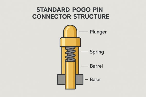
product or fixture already provides positioning and retention.
When Does Adding Magnets Create Real Value?
A magnetic pogo pin architecture becomes particularly worth evaluating when
the product requires:- frequent removable connections;
- blind or low-effort mating;
- one-handed cable attachment;
- automatic docking;
- controlled breakaway;
- a shallow external connection surface;
- a replaceable cable or module-side interface.
In these applications, magnetic capture and retention can become part of the
product function rather than an unnecessary extra component.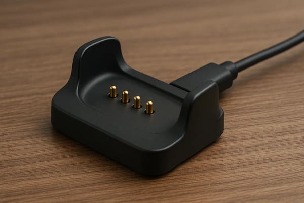
easy approach and repeated attachment are part of the product workflow.
A Better Selection Method: Start with the Retention Requirement
Instead of asking whether magnetic pogo pins are “better,” use the following
decision sequence:


    Pogo Contact Architecture Selected
    ↓
    How Will the Two Assemblies Be Retained?
    ↓
    Does the Product Already Provide Retention?
    ↓
    Is Frequent Removable Mating Required?
    ↓
    Does Magnetic Capture Add Useful Alignment Assistance?
    ↓
    Is Controlled Breakaway Valuable?
    ↓
    Can Metallic Debris and Magnetic Compatibility Be Managed?
    ↓
    Does the Added Cost / Space Create Product-Level Value?
    ↓
    Select Standard or Magnetic Architecture
Practical Decision Matrix
| Product Requirement | Standard Pogo | Magnetic Pogo |
|---|---|---|
| Internal Fixed Interface | Often a strong option | May add unnecessary complexity |
| Mechanical Fixture Already Exists | Often sufficient | Evaluate only if capture adds value |
| Frequent User Mating | Possible with suitable housing | Often worth evaluating |
| Blind Mating | Possible with mechanical guidance | Magnetic capture can reduce approach burden |
| Controlled Breakaway | Requires another release mechanism | Can be built into the magnetic interface |
| Positive Lock Required | Mechanical latch may be preferable | Magnetic-only retention may not be sufficient |
| Metal Debris Environment | Fewer magnetic debris concerns | Requires dedicated debris analysis |
| Lowest Architecture Cost | Can be advantageous if retention already exists | Must justify added magnets and assembly |
Electrical Performance Should Not Be Assumed from the Retention Architecture
Another important distinction is that adding magnets does not automatically
increase:- current capability;
- data bandwidth;
- contact resistance performance;
- mating life;
- waterproofing.
These characteristics depend on their own engineering variables.For current
Evaluate the complete conductive path:


    Source
    →
    Termination
    →
    Pogo
    →
    Contact Interface
    →
    Target
    →
    Load


Current capability should be supported by voltage-drop and temperature-rise
testing under representative conditions.
For signals
Review:- Pin Map;
- signal-to-return arrangement;
- contact geometry;
- PCB transitions;
- FPC or cable;
- complete channel.
Pin count does not prove bandwidth.For environmental protection
Review the complete sealing boundary.

Magnetic attachment, a flat surface or an O-ring does not by itself establish
an IP rating.
Information Needed Before Choosing Standard or Magnetic Pogo Pins
| Project Input | Information to Define |
|---|---|
| Connection Type | Internal, external, docking, module or test interface |
| Mating Frequency | Occasional, repeated or automatic |
| Retention | Who holds the two assemblies together? |
| Breakaway | Should the interface remain locked or intentionally release? |
| Mechanical Envelope | Available X, Y and Z space |
| Working Stroke | Minimum, nominal and maximum compression |
| Mating Tolerance | X-Y-Z and angular variation |
| Pin Map | Power, return, detection and signal functions |
| Electrical Load | Voltage, current and duty cycle |
| Environment | Water, dust, sweat, chemicals or metallic debris |
| Lifecycle | Expected service and mating profile |
| Cost Target | Component versus complete interface cost |
Frequently Asked Questions
What is the difference between standard and magnetic pogo pin connectors?
Both use spring-loaded contacts. The main difference is that standard pogo
connectors normally rely on another mechanical structure for retention,
while magnetic pogo connectors add magnet-assisted capture and retention.
Are magnetic pogo pin connectors better than standard pogo pins?
Not universally. Magnetic connectors are useful when easy removable mating,
magnetic capture or breakaway provides product-level value. Standard pogo
connectors can be simpler when the product already provides mechanical
positioning and retention.
Can standard pogo pin connectors support blind mating?
Yes. Mechanical guides, chamfers, fixtures and datums can create reliable
blind-mating systems without magnets.
Do magnets align pogo pins perfectly?
No. Magnetic attraction can assist capture, while mechanical datums and stops
should normally establish the final X-Y-Z position.
Do magnetic pogo pin connectors have better vibration resistance?
Not automatically. Dynamic performance depends on retention, working stroke,
contact force, mechanical movement and the actual vibration profile. The
electrical circuit should be monitored during relevant testing.
Do magnetic pogo pin connectors have a longer lifecycle?
Not necessarily. Lifecycle depends on contact materials, surface finish,
working stroke, alignment, contamination, electrical loading and test
conditions.
Are magnetic pogo pins easier to connect?
Magnetic capture can reduce the alignment effort during final approach,
especially for frequently removable or blind-mating interfaces. The amount
of benefit depends on product geometry.
What is partial mating in a magnetic pogo pin connector?
It is a state where magnetic attraction or some contact engagement occurs
before the connector reaches its fully seated mechanical position.
Do magnetic pogo pins carry more current than standard pogo pins?
Not because they are magnetic. Current capability depends on contact design,
working stroke, mating target, termination, complete-path resistance,
thermal environment and duty cycle.
Are magnetic pogo pin connectors waterproof?
Not automatically. The final ingress protection depends on the complete
connector and enclosure sealing architecture and must be validated on the
defined assembly.
What are the disadvantages of adding magnets?
Additional considerations can include magnet cost, package area, assembly
complexity, metallic-debris attraction, nearby magnetic-sensitive
components and the need to control separation behavior.
When should I choose a magnetic pogo pin connector?
It is especially worth evaluating when the product requires frequent
removable mating, easy capture, automatic docking, controlled breakaway or
a user-facing shallow connection interface.
When should I choose a standard pogo pin connector?
A standard architecture can be effective when the product, fixture or
enclosure already provides accurate positioning and reliable mechanical
retention.
Request a Pogo Pin Interface Engineering Review
Review

    CTP pogo pin and spring-contact connector solutions

for mechanically retained connector architectures.

Explore

    CTP custom magnetic connector solutions

for removable, docking and magnet-assisted interfaces.

Learn more about CTP engineering and manufacturing capabilities on the

    About Us page
. Submit your connector envelope, mating frequency, retention method,
Pin Map, working stroke, voltage, current, environment and available 2D
or 3D files to CTP for an engineering review.
The interface can be evaluated around one central question:
whether magnetic capture and retention add meaningful product-level
value or whether the existing mechanical structure can already support
the spring-contact interface.
Final electrical performance, lifecycle, environmental protection and
dynamic stability should be confirmed against the approved connector
revision and project-specific validation conditions.
CTP ENGINEERING PATHS
Choose the right path for your project
Move from application requirements to a connector pair, a data-capable cable assembly, or a charging cable configuration. Final specifications are confirmed against an approved drawing and project validation plan.
Magnetic Connectors
Connector geometry, pin layout, mechanical integration and OEM/ODM review.
Engineering overview → 02Magnetic Data Cables
Power and signal allocation, cable exit, interface selection and assembly review.
Cable engineering → 03Magnetic Charging Cables
Browse the complete cable catalog and shortlist a starting structure for customization.
View cable catalog →