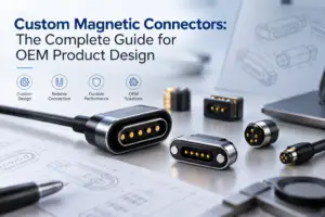
Precision machined pin receptacles, spring-loaded pogo pins and magnetic pogo pin connectors solve different interconnect problems. A receptacle accepts a defined solid mating pin, a pogo pin applies spring force against a mating surface, and a magnetic connector combines spring-loaded contacts with a magnet-assisted housing. The correct choice depends on mating geometry, assembly process, replacement needs, dimensional tolerance and user interaction.
A precision machined pin receptacle should not be treated as an early version of a magnetic pogo pin connector. The two interfaces use different mating mechanisms and are normally selected for different product requirements.
A machined pin receptacle is designed to receive a solid mating pin or component lead. A spring-loaded pogo pin contains a moving plunger that compresses against a target contact. A magnetic pogo pin connector adds magnets, a housing and mechanical locating features to create a detachable docking or cable interface.
This guide explains how these connector types differ, how precision machined pin receptacles are constructed and when a project should use a receptacle, a spring-loaded contact or a magnetic connector.
What Is a Precision Machined Pin Receptacle?
A precision machined pin receptacle is a female electrical contact designed to accept a defined mating pin, terminal or component lead.
A typical receptacle may contain:
- A precision-machined outer shell
- An internal multi-finger contact clip
- A solder, press-fit, swage or wire termination
- An opening sized for an approved mating-pin range
- A plating system selected for the electrical and environmental requirements
The internal contact clip is normally inserted into the machined shell. When the mating pin enters the receptacle, the contact fingers deflect and apply normal force around the pin.
This structure can provide several contact points around the mating lead while allowing the machined shell to control mounting, retention and alignment.
The Main Components of a Machined Pin Receptacle
| Component | Primary Function | Engineering Inputs |
|---|---|---|
| Machined shell | Supports the contact clip and mounts the receptacle | Outer diameter, mounting feature, material and plating |
| Contact clip | Applies contact force to the mating pin | Pin acceptance range, insertion force, material and finish |
| Mating pin | Enters the contact clip and completes the circuit | Diameter, shape, finish, straightness and insertion depth |
| Termination | Connects the receptacle to a PCB or wire | Solder tail, press-fit, swage, surface mount or wire termination |
| PCB or insulator | Positions and supports the receptacle | Hole size, thickness, material and positional tolerance |
How Does the Receptacle Make Electrical Contact?
The electrical connection is created when the mating pin enters the internal contact clip.
The contact result depends on:
- Mating-pin diameter
- Mating-pin shape
- Contact-finger geometry
- Insertion depth
- Contact and pin surface finishes
- Alignment during insertion
- Contamination and wear
The receptacle should therefore be selected together with its mating pin. It is not sufficient to specify only the PCB hole or outside diameter of the receptacle.
Pin Acceptance Range
A receptacle contact is normally designed to accept a defined range of mating-pin sizes.
The approved range may vary by:
- Contact-clip design
- Number and shape of contact fingers
- Required insertion force
- Pin geometry
- Material and plating
A wider acceptance range can help accommodate selected pin-size variation, but it should not be described as unlimited tolerance compensation.
The mating pin must remain within the supplier-approved dimensional and surface requirements.
Insertion and Extraction Force
The force required to insert or remove a pin depends on:
- Contact-clip geometry
- Mating-pin diameter
- Pin surface finish
- Number of receptacles in the connector array
- Alignment
- Lubrication or contamination where applicable
In a multi-position connector, the total insertion force may become significantly greater than the force of one receptacle.
The product team should therefore calculate or measure connector-level insertion force rather than reviewing one contact in isolation.
Common Precision Receptacle Mounting Methods
1. Through-Hole Solder Mount
A through-hole solder receptacle is installed into a PCB hole and electrically secured through soldering.
The design should define:
- Finished PCB hole diameter
- Receptacle mounting diameter
- PCB thickness
- Annular ring
- Soldering method
- Solder fill or fillet requirement
- Clearance to internal copper layers
Some receptacles include a standard solder tail extending through the PCB, while others use a shell-mounted solder structure without a separate tail.
2. Press-Fit Mounting
A press-fit receptacle is mechanically inserted into a controlled PCB hole or insulator.
The installation depends on the relationship between:
- Receptacle press-fit geometry
- Finished hole size
- Hole plating
- PCB or insulator material
- Board thickness
- Insertion force
- Support tooling
A properly engineered press-fit structure may eliminate a soldering operation. However, the hole and receptacle must be designed as one controlled fit system.
Do not assume that every machined receptacle can be pressed into any plated or non-plated hole.
3. Swage Mounting
A swage receptacle contains a section that is mechanically deformed after insertion to retain the contact in the PCB, panel or insulator.
This mounting method requires control of:
- Hole diameter
- Substrate thickness
- Swage-tool geometry
- Applied forming force
- Support fixture
- Post-forming dimensions
The swage operation should retain the receptacle without cracking the substrate, distorting the contact shell or changing the mating-pin acceptance.
For a detailed review of the forming process, see the related swage pin assembly engineering guide.
4. Surface-Mount or Low-Profile Mounting
Selected machined contacts and targets may be designed for surface-mount assembly.
The PCB assembly review should include:
- Recommended land pattern
- Paste-mask opening
- Component stability during reflow
- Pick-and-place packaging
- Installed height
- Inspection access
Surface-mount availability is product-specific. It should be confirmed from the selected receptacle drawing rather than assumed for the entire product category.
5. Wire-Termination Receptacles
Some receptacle designs terminate directly to a wire through crimping, soldering or another controlled wire process.
The specification should define:
- Wire size
- Conductor type
- Crimp or solder tooling
- Stripping length
- Pull-force requirement
- Insulation support
- Traceability and inspection
The receptacle-to-wire joint and the pin-to-receptacle interface are separate connection points and should be evaluated separately.
Precision Machined Receptacles and Pogo Pins Use Different Mating Principles
| Feature | Machined Pin Receptacle | Spring-Loaded Pogo Pin |
|---|---|---|
| Mating component | Defined solid pin, terminal or lead | Flat pad, target contact or another mating surface |
| Contact movement | Contact clip deflects around the inserted pin | Plunger moves axially inside the barrel |
| Normal force | Generated by contact fingers around the pin | Generated by an internal compression spring |
| Mating motion | Pin insertion and extraction | Surface compression and release |
| Tolerance compensation | Defined mating-pin acceptance range | Defined axial working-stroke range |
| Common use | Plug-in components, pins, leads and replaceable modules | Battery contacts, docks, test fixtures and surface-to-surface connections |
What Is a Spring-Loaded Pogo Pin?
A pogo pin is a spring-loaded electrical contact containing a plunger, barrel and internal spring.
When the mating surfaces come together, the plunger compresses and the internal spring provides contact force.
The important design parameters include:
- Free height
- Total travel
- Minimum, nominal and maximum working stroke
- Spring force at defined compression positions
- Plunger-tip geometry
- Contact resistance
- Mounting and termination method
Pogo pins are useful when the interface requires compliance between two surfaces rather than insertion of a long solid lead into a socket.
What Is a Magnetic Pogo Pin Connector?
A magnetic pogo pin connector combines a spring-loaded contact system with magnets, a connector housing, mating targets and mechanical locating features.
The system normally separates the following functions:
- Pogo pin spring: Provides electrical contact pressure
- Magnets: Assist capture and connector retention
- Housing: Controls orientation and lateral alignment
- Mechanical stop: Defines final pogo pin compression
- Mating pads: Complete the electrical path
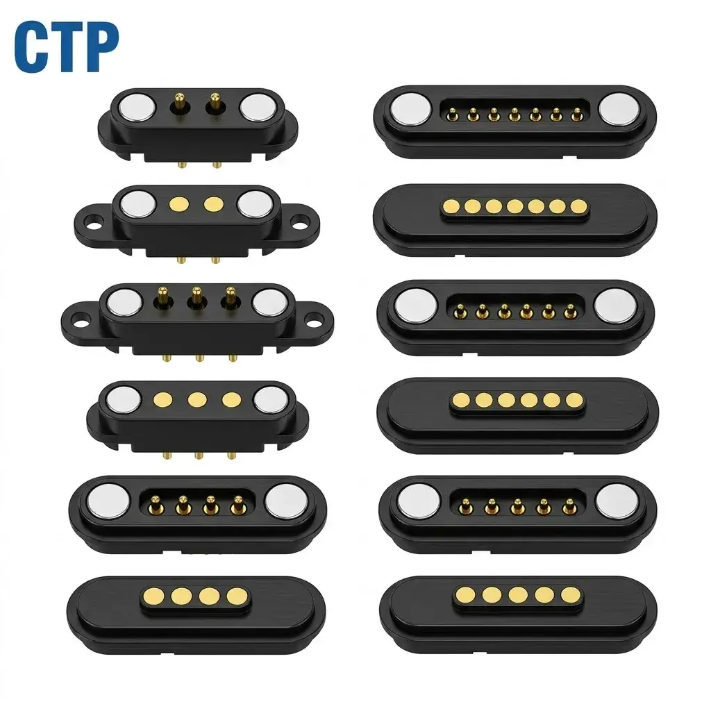
The magnets do not replace the pogo pin spring, and they do not independently define the final connector position.
Magnetic Pogo Pins Are Not a Universal Replacement for Pin Receptacles
Replacing a receptacle with a magnetic connector changes the complete mechanical and electrical architecture.
The change may affect:
- Mating direction
- Available installation area
- PCB layout
- Connector height
- Retention and release force
- Pin Map
- Electrical sequencing
- User interaction
- Environmental sealing
- Accessory compatibility
A magnetic interface may be suitable when a product requires easy docking or cable breakaway. A pin receptacle may remain more suitable when a positive plug-in pin connection or component replacement interface is required.
When Should You Use a Precision Machined Pin Receptacle?
A receptacle may be appropriate when:
- A solid pin or component lead already exists
- The connected component must be removable
- A plug-in IC, module, relay or sensor is required
- The interface needs a defined insertion depth
- A dense array of fixed mating pins is used
- Press-fit, swage or solder-mounted socketing is preferred
- The design does not need magnetic docking or breakaway behavior
Typical use cases may include:
- Socketed electronic components
- Board-to-board pin arrays
- Plug-in modules
- Replaceable sensors
- Wire-to-pin connections
- Test and measurement assemblies
When Should You Use a Spring-Loaded Pogo Pin?
A pogo pin may be more suitable when:
- The interface mates with a flat conductive surface
- Axial tolerance compensation is required
- The mating part should not contain a protruding solid pin
- The connection is temporary or repeatedly compressed
- A battery, test fixture or docking interface is required
- A low-profile target pad is preferred
Examples include:
- Battery contacts
- Charging cradles
- Production test fixtures
- Board-to-module contacts
- Wearable-device charging interfaces
- Replaceable device modules
When Should You Add a Magnetic Mating Structure?
A magnetic structure may be useful when:
- The user needs simple docking
- The cable should detach under a controlled pull
- Repeated manual insertion of a rigid plug is undesirable
- The product requires a custom charging interface
- The device requires a defined removable module
- The interface must be positioned with one hand
Magnetic mating also introduces additional design requirements:
- Magnetic capture and holding force
- Breakaway direction
- Incorrect-mating prevention
- Final mechanical location
- Pogo pin working stroke
- Metallic-particle contamination
- Magnet retention and coating
A magnetic connector should not be selected solely because it is newer or visually different.
Connector Architecture Selection Matrix
| Project Requirement | Likely Starting Architecture | Reason |
|---|---|---|
| Plug-in solid component lead | Machined pin receptacle | Designed to receive a defined mating pin |
| Replaceable pin-based module | Pin and receptacle system | Provides controlled insertion and extraction |
| Surface-to-surface battery contact | Spring-loaded pogo pin | Provides axial compliance against a target pad |
| Production testing interface | Pogo pin or test probe | Supports repeated temporary contact |
| Charging dock | Pogo pin connector or magnetic connector | Supports repeatable surface contact |
| Detachable charging cable | Magnetic pogo pin connector | Adds capture, retention and controlled release |
| Positive locked industrial connection | Locking connector or receptacle system | Magnetic breakaway may not meet the retention requirement |
| Standardized external interface | Applicable standard connector | Preserves cable and accessory interoperability |
Key Design Inputs for a Machined Pin Receptacle
Mating-Pin Diameter and Shape
Define:
- Minimum pin diameter
- Nominal pin diameter
- Maximum pin diameter
- Round, square or rectangular section
- Lead-in geometry
- Straightness
- Surface finish
- Permitted burrs or edge conditions
The receptacle contact must be approved for the actual pin geometry.
Pin Insertion Depth
Insufficient insertion may engage too little of the internal contact. Excessive insertion may interfere with the bottom of a closed receptacle or surrounding PCB structure.
Define:
- Minimum engagement
- Nominal engagement
- Maximum permitted insertion
- Mechanical stop
- Pin protrusion through open-bottom receptacles
PCB Hole and Mounting Fit
The PCB drawing should identify:
- Plated or non-plated hole
- Finished-hole diameter
- Board thickness
- Position tolerance
- Annular ring
- Press-fit or clearance-fit requirement
- Soldering process where applicable
The drill diameter and finished-hole diameter should not be treated as the same value.
Connector Pitch and Alignment
In a multi-receptacle array, the receptacle positions must match the mating-pin positions.
Review:
- Pin pitch
- Hole-position tolerance
- PCB and housing datums
- Mating-part flatness
- Angular misalignment
- Total insertion force
One receptacle may accommodate limited pin variation, but a large array can bind when the cumulative positional error becomes excessive.
Do Not Apply Universal Performance Numbers
Mechanical life, current, contact resistance, vibration and shock results belong to a specific receptacle family or part number.
For example, published commercial receptacle specifications may define:
- A specific mating-pin acceptance range
- A minimum mechanical life
- A maximum initial resistance
- A current rating under a defined temperature-rise condition
- A vibration or shock profile
Those values should not be copied to another receptacle, a CTP pogo pin or a magnetic connector without confirming design equivalence and test conditions.
The engineering specification should state:
- Exact part number and revision
- Mating pin
- Mounting condition
- Test method
- Sample state
- Acceptance criteria
Materials and Plating Must Be Part-Specific
A machined receptacle may use different materials for the outer shell and internal contact clip.
The material stack may include:
- Machined copper-alloy shell
- Beryllium-copper or another approved contact material
- Nickel underplate
- Gold, tin or another functional finish
- Selective termination plating
No single alloy or finish is automatically correct for every product.
Review:
- Electrical current
- Mating frequency
- Insertion force
- Operating temperature
- Environmental exposure
- Soldering or press-fit process
- Mating-pin finish
Production Packaging and Automated Placement
Selected receptacles, spring-loaded contacts and mating targets may be available in tape-and-reel packaging for automated placement.
Packaging suitability should be confirmed from the specific product drawing and ordering code.
The manufacturing review should include:
- Carrier-tape dimensions
- Component orientation
- Pick-up surface
- Nozzle compatibility
- Placement accuracy
- Feeder compatibility
- Post-placement stability
Tape-and-reel packaging does not by itself prove that the component is suitable for reflow. The termination and material system must also be approved for the selected assembly process.
Validation Matrix
| Requirement | Possible Evaluation | Output |
|---|---|---|
| Mating-pin compatibility | Minimum, nominal and maximum pin-size evaluation | Insertion, retention and electrical results |
| PCB mounting | Hole, press-fit, swage or solder-process trial | Installed position and retention |
| Insertion and extraction force | Force measurement on one contact and full array | Force-displacement data |
| Electrical resistance | Defined contact-resistance measurement | Initial and post-conditioning values |
| Current capability | Voltage-drop and temperature-rise evaluation | Current, voltage and stabilized temperature |
| Repeated mating | Project-defined insertion and extraction cycles | Force, resistance and wear change |
| Mechanical environment | Application-specific vibration and shock testing | Continuity and post-test condition |
| Mating alignment | Worst-case positional tolerance review | Successful mating and evidence of binding |
Common Selection Mistakes
| Mistake | Possible Consequence | Better Approach |
|---|---|---|
| Calling receptacles an earlier generation of pogo pins | The wrong mating architecture may be selected | Treat receptacles and pogo pins as different connector systems |
| Selecting only by outside diameter | The mating pin may not fit the contact clip | Confirm the complete mating-pin acceptance range |
| Ignoring insertion force in a multi-pin array | The full connector may become difficult to mate | Calculate and measure total connector force |
| Using a press-fit receptacle in an uncontrolled hole | Loose retention or PCB damage | Define the receptacle, hole and installation tooling together |
| Applying one supplier’s performance to another part | Current, life and vibration claims may be unsupported | Use part-specific drawings and test data |
| Assuming magnetic connectors are always more reliable | The project may lose positive retention or compatibility | Select from the actual mating and user requirements |
| Using magnetic connector photos as receptacle cross-sections | The article misrepresents the component structure | Use an original receptacle diagram with accurate labels |
| Claiming CTP manufactures receptacles without product evidence | Customers may request a product line that is not available | Describe architecture selection and link to confirmed CTP product families |
Engineering Reference Sources
The following manufacturer sources illustrate the structural difference between machined pin receptacles, mating pins, spring-loaded contacts and mating targets. Specifications must still be confirmed for the selected product.
-
Mill-Max — Pins and receptacles: machined shells and multi-finger contact clips
-
Mill-Max — Zero-profile press-fit receptacle construction
-
Mill-Max — Through-hole solder-tail receptacle example
-
Mill-Max — Swage-mount receptacle example
-
Mill-Max — Wire-termination receptacle example
-
Harwin — Spring-loaded pogo pins and mating contact pads
-
Mill-Max — Precision-machined SMT targets for spring-loaded pins
Frequently Asked Questions
Is a machined pin receptacle the same as a pogo pin?
No. A receptacle receives a solid mating pin through an internal contact clip. A pogo pin contains a spring-loaded moving plunger that compresses against a mating surface.
Are magnetic pogo pins an upgraded version of pin receptacles?
No. They are different connector architectures. A magnetic pogo pin connector is selected when magnet-assisted docking, surface contact or controlled breakaway is required. A receptacle remains suitable for plug-in pins and replaceable components.
What determines the mating-pin size for a receptacle?
The internal contact-clip design defines an approved mating-pin acceptance range. The pin diameter, shape, finish and straightness should remain inside the selected receptacle specification.
Can one receptacle accept round and square pins?
Some commercial contact-clip designs can accept more than one lead shape, but this is product-specific. The exact mating geometry should be confirmed from the supplier drawing.
Can a receptacle be press-fitted without soldering?
Selected receptacles are designed for controlled press-fit installation. The receptacle geometry, finished hole, PCB material and tooling must be specified together.
What is the difference between press-fit and swage mounting?
A press-fit relies on an interference relationship during insertion. A swage structure is mechanically formed after insertion to retain the receptacle in the substrate.
Does a machined receptacle always provide a model-specific cycle-life target validated under defined test conditions?
No. Mechanical life is specific to the receptacle design, contact clip, mating pin, plating and test conditions. A universal cycle value should not be applied to all receptacles.
When is a pogo pin better than a receptacle?
A pogo pin may be preferable when the interface needs axial compliance, a flat mating target, repeated temporary contact or a charging and docking structure.
When should magnets be added to a pogo pin connector?
Magnets may be added when the product needs assisted docking, connector retention or controlled cable release. The housing and mechanical stops must still control final alignment and working stroke.
What information is required for connector architecture selection?
Provide the mating geometry, PCB and enclosure dimensions, electrical functions, current, voltage, expected mating frequency, mounting process, environment and required user interaction.
Prepare an Interconnect Architecture Review
Before selecting a receptacle, pogo pin or magnetic connector, prepare:
- Application and device description
- Mating component or target geometry
- Pin count and Pin Map
- Voltage and current
- Signal or data requirements
- PCB and enclosure dimensions
- Available mounting process
- Required mating and removal force
- Expected mating frequency
- Environmental exposure
- Required retention or breakaway behavior
- Expected production quantity
Review available individual pogo pins, compare pogo pin connector assemblies, explore custom magnetic connector structures, or access additional engineering guides.
Submit your mating geometry, PCB drawings and electrical requirements through the Get Quote & Samples page.
CTP can review whether an application is better suited to an individual spring-loaded contact, a multi-pin pogo pin connector or a custom magnetic connector. Final dimensions, materials, electrical ratings and validation criteria should be confirmed in the approved project drawings.