The most convenient place for a connector is sometimes the side of the product. A desktop accessory should be easy to reach. A removable module may slide into a narrow opening. The main PCB, meanwhile, may lie in a direction that does not suit a straight contact termination.
Our right-angle pogo pins and connector arrays help bring those directions together. The spring-contact face can meet the accessory from the side while the bent terminals connect to the board. For right angle pogo pin alignment, that gives you a practical starting shape around which to arrange the enclosure and mating targets.
A bent-tail contact gives the board another connection route
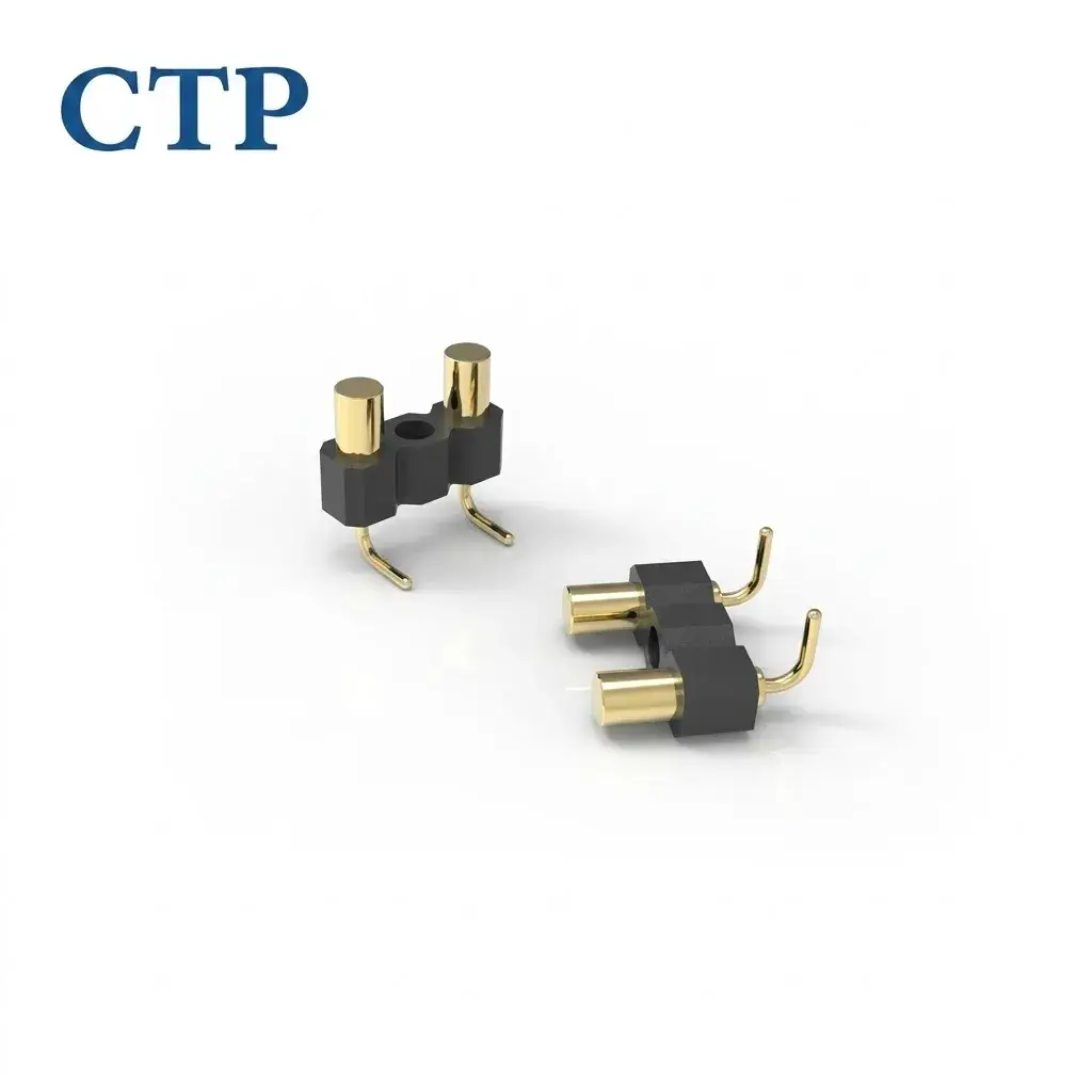
The CTP individual right-angle pogo pin, CTP-PP-1P-RA-HC-A01, has an axial spring plunger and a visibly bent termination tail. It provides one electrical path where a straight termination would be awkward within the available space.
This can suit an instrument with an accessory connection near its front edge. The PCB can remain positioned for the rest of the electronics, while the contact reaches a mating target from a more convenient direction. The termination and the user-facing interface no longer have to follow the same straight line.
The bent termination leaves the spring plunger its own job
The contact tip still moves along its axis to apply electrical pressure. The bent tail routes that contact into the device. Separating those functions makes the part easier to understand within the complete product: the contact meets the target, and the tail suits the board arrangement behind it.
An individual pin also gives the designer freedom over spacing. Two separated target pads can be served by separately positioned contacts, without requiring one connector housing to span the gap. That is helpful when the device has a locating feature or another component between the electrical positions.
The benefit is a side-facing connection that follows the product layout. It can keep an accessory accessible while leaving useful room inside for the PCB and other parts. The surrounding guides establish how the accessory approaches and where it finally sits.
Two contacts can make a neat, narrow interface
Our two-contact right-angle connector, CTP-PC-2P-SR-A01, brings two spring contacts into a single-row housing. It gives a small interface one recognizable contact pattern rather than two independent component bodies to arrange.
A shared two-contact housing keeps the pair together
For a compact accessory needing two assigned electrical paths, the short row can be considered beside the product’s guides and opening. The housing maintains the relationship between the contact positions while the plungers provide the spring action at the targets.
A small device may benefit from that simplicity. Its contact area can remain narrow, and the board designer has one connector outline to position. The actual electrical functions come from the device circuit, so the two positions are defined for the product instead of assumed from their appearance.
The same product thinking applies to the matching target area. A pair of pads can be located where the accessory naturally reaches the connector. The enclosure then supports the mating action, allowing the contact face to remain a small part of the overall design.
Right angle pogo pin alignment follows the way the accessory arrives
Alignment means bringing the contact tips and matching targets together in the intended position. In a side-facing arrangement, the direction of approach matters. A housing guide can lead the accessory toward the contacts before the final spring compression occurs.
This is especially useful when the product is connected by feel. A desk instrument might sit under a display, making its underside difficult to reach. Moving the contact interface to an accessible edge can give the user a more natural connection point, provided the surrounding product guides that action appropriately.
The guide to contact alignment and tolerances gives more detail on the assembled relationship. During selection, compare the connector face with the target position and the space behind the board. A right-angle format is valuable when those directions are a genuine match for the device.
The plunger is not used as a lateral guide. The product structure brings the target toward it, and the spring supplies movement along the contact axis. Keeping that simple relationship in mind helps the connector fit smoothly into the action the user is meant to make.
Five inline contacts add room for the device’s other functions
The CTP five-contact right-angle connector, CTP-PC-5P-SR-A01, uses a single-row housing with bent PCB tails. It offers more assigned electrical positions while keeping a linear side-facing arrangement.
A removable control accessory may need power and reference alongside additional supported functions. A five-contact interface provides paths to define for that circuit. The functions belong to the connected electronics; the connector gives them a coordinated physical route across the removable interface.
For the product designer, the linear shape can follow a narrow edge. The contact area can sit beside an enclosure opening while the bent tails meet the PCB inside. That can be more convenient than moving the whole board simply to put a straight connector in the desired external position.
The five-contact format also offers a clear middle option between two contacts and a larger array. If the circuit needs only that number of paths, the connector can be selected around them without reserving an unnecessarily large mating area.
A dual-row array brings more paths into the side-entry design
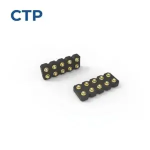
Our ten-contact dual-row right-angle array, CTP-P3577, uses a five-by-two layout with bent PCB tails. It suits the comparison when more paths are needed within a rectangular contact area.
Five-by-two contacts can serve a removable electronics module
A module with several assigned signals may need more than a short power interface. The dual-row housing gives those paths a shared physical pattern, while the right-angle tails preserve a different direction for the board connection. The module’s target area can then be developed around one defined connector shape.
For a larger instrument, that can keep the removable interface concentrated at one edge. It gives the module a clear connection zone while leaving the rest of its enclosure and board available for other functions. Each spring contact remains one part of the complete mating action.
The choice between a five-position row and a ten-position block is therefore about both circuit needs and available shape. A larger count is worthwhile when those paths are useful. The selected pattern should still fit the way the module is located and removed.
A magnetic option combines side-entry contacts with assisted capture
Side-entry design is also worth considering when the product is used close to a wall or mounted beside other equipment. An interface that is convenient on an open bench may be difficult to reach in its installed location. The board can retain its useful position while the contact face is placed at an accessible edge.
For a small removable accessory, the two-contact row may leave the surrounding area simpler. For a more capable control module, the five-contact row adds electrical positions without changing to a two-row outline. The ten-contact block offers another shape where the circuit needs more paths. Those differences help the connection follow the product’s actual use.
The individually positioned bent-tail pins remain valuable where none of those grouped patterns suits the target pads. Their positions can follow separate locations in the housing. This can avoid occupying the area between the contacts when another product feature already sits there.
Comparing the complete components gives the design team more than a drawing of a bent terminal. It shows how each option combines its contact face, housing outline and board connection, making the benefits of a side-facing interface easier to judge in the real device.
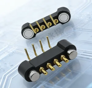
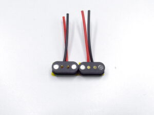
The CTP four-contact right-angle magnetic connector, CTP-MPC-4P-RA-TH-01, combines a four-contact interface with bent PCB terminals and magnetic mating features. It is a direct-board option where magnetic capture is part of the desired connection.
The magnets assist the two parts as they approach and help retain the seated connection. The spring contacts provide electrical pressure. The housing and device structure still define the final position, giving each element a clear role in the product.
This can be appealing for an accessory that should attach conveniently at the side of a compact device. It offers a different user interaction from a non-magnetic contact array held by the product’s own retention mechanism. The right choice follows the attachment and removal action you want.
Across the range, the common advantage is freedom over where the electrical face meets the user. An individual bent-tail pin, a short row, a dual-row array and a magnetic PCB connector bring different combinations of shape and contact count. Compare them with the actual board and accessory, and the side-facing connection can become a natural part of the product.