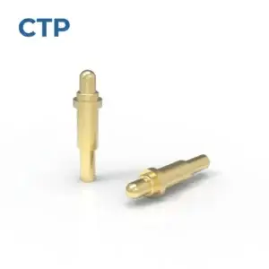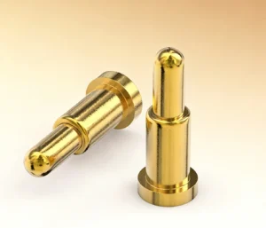
A straight mounting tail can be exactly what a board design needs. It gives the spring contact a direct through-hole connection to the PCB while the working tip faces the mating surface. For equipment built around that arrangement, our DIP pogo pins offer a simple way to bring a removable electrical interface into the product.
CTP’s through hole pogo pin mounting options include individual contacts, a shouldered body and integrated single-row or dual-row arrays. You can choose the contact pattern around the board and the matching device, whether the product needs one separated point or several neighboring paths.
Individual DIP contacts give you freedom over spacing
The CTP through-hole spring-loaded pogo pin, CTP-PP-TH-A01, combines a moving plunger, cylindrical body and straight PCB tail. It is one electrical contact, so each position can be placed to suit its corresponding target.
That is attractive when the target layout belongs to the product rather than a standard rectangular connector. A charging cradle might need a contact on each side of a locating post. A removable accessory might present two separated pads beside a central housing feature. Individual pins can follow those positions.
A straight PCB tail separates the board joint from the moving tip
The tail forms the through-hole board connection, while the spring-loaded end meets the removable part. This gives the two ends distinct jobs in the assembly. The board and housing establish the contact’s installed position, and the plunger provides the movement needed at the electrical interface.
For the product designer, that is a straightforward arrangement to visualize. You can see the board connection below the contact body and the target above it. The part can be considered with the available board thickness, space beneath the PCB and the position of the mating surface.
A contact that fits the board in this way can leave the outside of the device pleasantly simple. The user sees a small target area or docking position, while the individual contacts sit within the structure behind it. The electrical connection follows the product’s normal mating action.
A shouldered body offers another installation profile
Our shouldered DIP pogo pin, CTP-PP-DIP-A02, has a stepped cylindrical body with an upper radial shoulder and a narrower straight tail. Its profile gives the mechanical designer a different shape to work with from a plain cylindrical contact.
The upper shoulder is a defined feature in the contact geometry
When a contact passes through a support or sits within a carrier, the shape around its body can be important to the layout. The shouldered format gives that discussion a visible feature to reference. Its exact seating or retaining role belongs in the selected drawing, so the component and carrier can be developed as one arrangement.
This is useful when the device needs more than an electrical point floating in a board layout. The contact may have to relate to an enclosure opening, a support plate or a removable module above it. Comparing the shouldered and straight-body formats lets you choose the profile that better suits those surrounding parts.
Our long-body DIP spring contact, CTP-PP-DIP-A01, provides another individual geometry. Its longer cylindrical form can be considered where the installation calls for a different reach or body arrangement. The required working position comes from the part and assembly drawing.
The advantage is choice within the same general mounting approach. You can retain a through-hole board connection while comparing contact profiles suited to different internal spaces, instead of redesigning the entire interface around one body shape.
Through hole pogo pin mounting can also serve a complete contact row
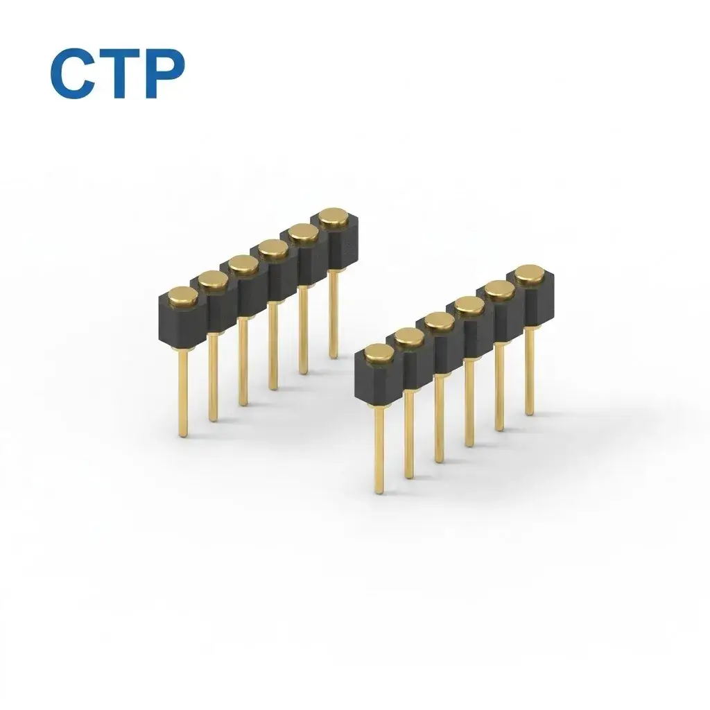
For several neighboring connections, a housing can bring the positions together. The CTP six-contact single-row through-hole connector, CTP-PC-6P-SR-A01, holds six spring contacts in a one-by-six arrangement with straight PCB tails.
Six inline positions make one clear target pattern
A linear arrangement can sit along a board edge or a narrow mating area. The contacts form one recognizable strip, which helps the designer coordinate the connector with the corresponding device targets. The housing keeps the relative positions together while the individual plungers provide spring action.
For a removable instrument module, that can bring several assigned functions to one accessible edge. The connector’s outline can be considered with the guides and supports that position the module. The result is an electrical interface that belongs to the device’s shape, with a board termination route that suits through-hole assembly.
Six positions can serve different circuit functions according to the product’s contact map. They are not tied to one charging or communication scheme. That flexibility is valuable when the connector should carry the particular combination of paths your device uses.
A dual-row connector gives more contacts a shorter outline
Our twelve-contact dual-row through-hole array, CTP-PC-12P-DR-A01, uses a six-by-two housing. It doubles the positions across two rows rather than extending all twelve contacts in a single line.
A compact control module may need that different shape. Two rows can fit a rectangular mating area where one long row would extend beyond the available edge. The layout also gives the board designer a defined connector body to arrange with other components and mounting points.
Each path remains independently assigned in the circuit. The shared housing organizes the physical positions, while the electronics determine what those positions do. This allows the product team to consider a grouped spring interface without treating the contact count as a promise of a particular protocol.
There is no reason to choose the largest array by default. The six-contact row may be more suitable for a narrow interface; individual pins may be better for separated pads. The twelve-contact block is most appealing when its extra paths and two-row shape match the product.
| If your board arrangement needs… | A CTP format to compare |
|---|---|
| Separated contact points around other features | Individual straight-tail DIP contacts |
| A stepped body profile within a support | The shouldered DIP contact |
| A narrow line of assigned electrical paths | The six-contact single-row connector |
| More paths within a rectangular area | The twelve-contact dual-row array |
Through-hole spring contacts can support a removable module
Imagine an equipment module that is removed for service. Its enclosure guides establish the position, the targets meet the spring contacts and the board tails remain part of the fixed assembly. The contact format supports separation at the intended interface without requiring the board connection itself to be disturbed.
For a desktop cradle, the same general idea can serve a different action. The user places the device into a supported pocket, and the pogo tips meet its pads as it settles. Individual contacts or a shared row can be chosen according to the target locations and the space available in the cradle.
The practical benefit comes from coordinating the contact with the product. The housing supports the mating part; the spring contacts provide electrical pressure. This lets the interface remain small and approachable while the internal mounting follows the board’s needs.
Our PCB mounting guide for spring-contact interfaces explains more about that relationship. The chosen drawing establishes the installed dimensions and working position for the particular contact or array.
Choose a DIP body or array around your target pattern
The choice also affects how naturally the contact pattern fits a later product variant. If a compact model needs only a few separated points, individual pins can follow its target locations. A larger module in the same development program may use a grouped connector instead. The product can keep a spring-contact approach while the physical format follows each board.
For a board with a busy upper surface, the contact body’s outline deserves attention alongside the tail. A cylindrical pin occupies a different area from a shared array housing. Looking at both profiles early helps preserve room for nearby components, housing supports and the mating target itself.
These are everyday design advantages rather than abstract mounting preferences. The connector is easier to integrate when its shape already suits the available area. It is also easier to describe the selected assembly when the drawing shows one clear contact format, its board relationship and the target it meets.
With the through-hole parts listed here, you can compare those profiles without changing the basic idea of a straight PCB termination and a spring-loaded mating face. That gives the product team room to refine the interface around the equipment it is building.
Through-hole mounting is a practical choice when it suits the PCB, available space and assembly route. The product range gives you individual cylindrical contacts, a shouldered profile and grouped arrays within that approach.
For your device, start with the target pattern and the way the two parts meet. A few separated pads may point toward individual DIP pins. A narrow contact edge may suit the six-position row. A more involved module may benefit from the twelve-position dual-row block.
Those are choices that can make the connection easier to integrate and easier to explain. The most suitable part is the one whose body, tail and spring-contact face fit the product together. Our DIP range provides several clear starting shapes for that conversation, without making every through-hole interface look the same.