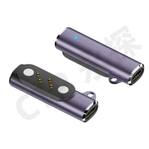
Ten electrical contacts do not have to mean ten separate parts to position on your board. With an integrated pogo pin array, the contacts sit together in a housing that gives the interface a defined shape. That can make a multi-contact connection much easier to fit into a compact product.
Our arrays range from short dual-row blocks to a long single row. Each spring-loaded contact has movement along its own axis, while the housing keeps the contact pattern together. For designers considering pogo pin array coplanarity, this is a useful starting point: a coordinated arrangement of contacts that can meet a matching set of targets.
A shared housing gives the contact pattern a clear shape
Our ten-contact SMT pogo pin connector, CTP-PC-10P-DR-A01, uses a five-by-two layout. The two rows keep ten positions within a relatively short contact block, rather than stretching them across a single line.
That arrangement can suit a removable control module or a compact board interface where several electrical functions need to meet in one place. The housing gives the PCB designer one connector outline to arrange around nearby components. The mating side has one defined target pattern to match.
The five-by-two array brings ten positions into one part
Holding the positions in a common housing reduces the number of separate contact bodies that need to be arranged individually. It also makes the intended pattern easier to recognize during product development. A designer can compare the complete block with the available opening instead of building the outline from loose pins.
The contacts can be assigned to the required circuit functions. Their number does not prescribe a protocol or a universal wiring scheme. This freedom lets the same basic array format be considered for different devices, with the actual electrical definition developed around each product.
For the finished device, the benefit is a purposeful contact area. Power, reference and other assigned connections can meet within one coordinated layout, while each pogo pin provides its own spring action at the mating surface.
Pogo pin array coplanarity is about the assembled interface
Coplanarity describes how closely a set of surfaces lies in the same plane. With a pogo connector, it helps to distinguish the board-mounting side from the tips that meet the targets. The complete connection includes the array, PCB, mating surface and product housing.
Spring movement gives each contact some ability to accommodate the intended variation along its axis. That is one reason these connectors are useful for separable assemblies. The product still needs a suitable seated position so that all the contacts operate within the selected working range.
For example, a compact module may settle against guides in the enclosure before the contacts reach their working position. The guides establish where the module sits; the plungers then apply contact pressure at the target pads. Thinking about those roles together helps the array become part of a smooth, repeatable connection.
Our contact-interface tolerance guide explains the assembled relationship in more detail. During product selection, the useful question is simple: which contact pattern and mounting style fit the way your two parts come together?
A smaller dual-row block can leave room for other components
The CTP eight-contact SMD array, CTP-PC-8P-DR-A01, arranges its contacts in four pairs. It is another option when the product needs several paths but the board area does not call for a longer connector.
Four-by-two contacts suit a short rectangular interface
Consider a portable instrument with a removable accessory near one corner. A short contact block may leave more freedom for the battery, display connections or mounting features elsewhere on the board. The connector can be considered alongside those parts early in the layout.
The eight-contact housing also presents the mating pattern as one unit. That can make the accessory’s target area easier to coordinate with its casing. The important advantage is the compact arrangement, rather than an assumption that eight contacts always provide the same functions.
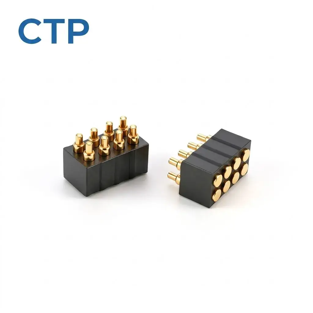
Choosing between the eight- and ten-contact formats can therefore be a product-layout decision as well as a circuit decision. The additional positions must be useful, and the complete connector has to sit comfortably within the board and mating surface available.
A long single row can follow the edge of a larger module
A compact block is not always the most convenient shape. Our thirty-contact single-row connector, CTP-PC-30P-SR-A01, brings thirty spring contacts into one long linear housing.
This format can be considered where the electrical interface runs along the edge of a board or module. The contact area is spread in one direction, leaving a different pattern of available space around it. A narrow linear strip can fit an arrangement where a deeper rectangular block would interfere with nearby parts.
For a removable electronics panel, that may help keep the connection along a defined edge while the rest of the panel remains available for components. The housing maintains the row as one assembly, which is useful when many contact positions belong to the same mating action.
The longer interface also makes the support of both mating parts worth considering from the start. A suitable product structure helps the full row meet its targets in the intended position. This is a layout choice to develop with the panel, rather than a contact strip to add after its mechanics are finished.
Through-hole arrays offer another board-mounting choice
Our sixteen-contact dual-row through-hole array, CTP-PC-16P-DR-A01, uses an eight-by-two housing and straight PCB tails. It gives the designer a grouped contact interface with a different mounting route from an SMD array.
Eight pairs of contacts can serve a more involved module
A device with several assigned signal and power paths may benefit from the additional positions. The straight tails connect through the PCB, while the spring contacts face the mating part. This keeps the board termination and the separable interface within one connector assembly.
If your board assembly is arranged around through-hole parts, this format is worth comparing with the smaller SMD blocks. The decision includes the available area on both sides of the board, the required contact pattern and the way the module is supported.
Another route is our custom ten-contact non-magnetic assembly, CTP-PPC-10P-01. It combines spring contacts with an insulating housing for product-specific integration. Where the device already has its own guides or fasteners, a non-magnetic connection can fit naturally into that structure.
A connector choice that follows the product’s outline
An array can also make the outside of a device easier to organize. A group of assigned functions can meet at one target area instead of needing several separate cable sockets around the housing. Whether that arrangement is useful depends on the circuit and accessory, but it gives the product designer another way to create a clean connection point.
Imagine a small docking accessory that handles both charging and a supported control function. A compact dual-row array can bring the required contacts together beside the device’s seating features. The product can then guide the accessory into place, while the individual plungers meet their targets. The array provides the paths; the connected electronics provide the actual functions.
For a larger replaceable panel, the long thirty-contact row may be the more natural shape. Its narrow outline can follow the panel edge and leave the center available for other components. This is a different benefit from simply adding more positions to a compact connector, and it is why the shape of the contact area deserves attention alongside the count.
Our non-magnetic ten-contact assembly is useful to compare when the product already includes a positive holding structure. An enclosure latch, guide or fastener can establish the mechanical relationship without adding magnets to the electrical part. The connector choice can therefore complement the way the device already works, rather than introducing another release action for the user.
Across these formats, the contact housing gives the mating pattern a recognizable identity. That helps when arranging the PCB, locating the target area and selecting a corresponding part for a later build. The spring contacts remain individual electrical paths within that shared shape.
The main appeal of an integrated array is the combination of a defined contact pattern and individual spring action. A short two-row connector, a long single row and a through-hole block each offer a different way to use that combination.
For your product, begin with the available mating area and the number of useful electrical paths. Then compare how the board and the removable part approach one another. Those details help narrow the choice without turning every project into a search for the largest possible contact count.
A well-matched array gives the connection an intentional shape. It can leave more useful room around the board, bring several functions into one interface and make the mating area easier to coordinate with the enclosure. Coplanarity remains part of the design review, but the product benefit is straightforward: a multi-contact connection built around the space and movement your device actually has.