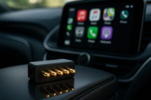
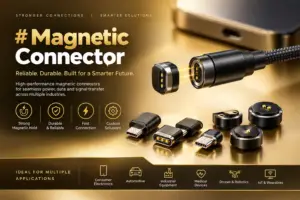
Medical grade magnetic connectors can support removable charging,
docking, sensor and accessory interfaces in medical equipment, but
medical suitability cannot be established from the connector architecture
alone. Engineers should define the clinical or operational function of the
connection, consequences of disconnection, mating-state behavior, cleaning
and disinfection exposure, patient-contact conditions, electrical
requirements and lifecycle before selecting a magnetic pogo pin interface.
Magnets can assist capture and retention while spring-loaded contacts
provide electrical conduction, but final medical-device safety and
performance depend on the complete system and its validation.
What Does “Medical Grade Magnetic Connector” Actually Mean?
The phrase medical grade magnetic connector is often used
commercially to describe a magnetic connector intended for integration into
medical or healthcare equipment.
Engineers should not treat the phrase itself as a standalone certification
or a supports that a connector is suitable for every medical device.
Suitability depends on the actual application.A medical-device development team may need to define:
- what function the connector performs;
- whether the connection affects an essential device function;
- whether it is accessible to the patient or operator;
- whether any surface contacts skin directly or indirectly;
- how frequently it is connected and disconnected;
- which cleaning or disinfection processes it experiences;
- what happens if the connector is partially mated;
- what happens if it disconnects unexpectedly;
- what electrical power or signals cross the interface.
Therefore, the engineering question should not simply be:

“Is this a medical connector?”
It should be:
    “Is this connector architecture suitable for the intended medical-device
    function, use environment and risk controls?”
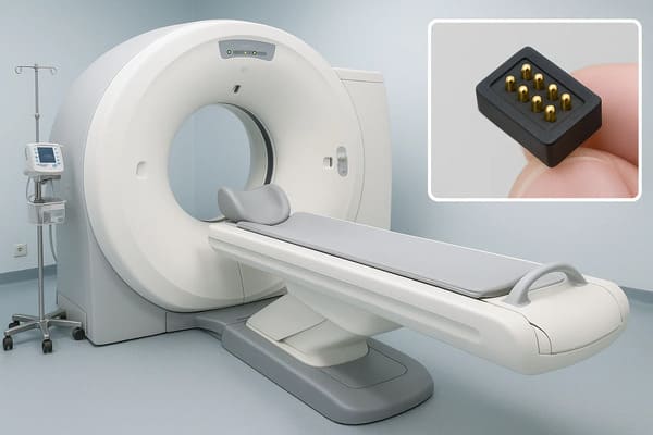
equipment connections, but the connector must be reviewed as part of
the complete device architecture and intended use.
Priority 1: Start with Connection Criticality, Not Connector Features
The same magnetic connector architecture can create very different risks
depending on what the electrical connection actually does.
For example, the interface may provide:
- battery charging while the device is not in clinical use;
- connection to a removable sensor;
- accessory identification;
- low-voltage auxiliary power;
- diagnostic communication;
- service or programming access;
- a connection required during active monitoring or therapy.
These functions should not be treated as equivalent.| Connector Function | Example Design Question |
|---|---|
| Offline Charging | What happens if charging is interrupted? |
| Removable Sensor | How is valid sensor attachment detected? |
| Accessory Interface | Can the system identify the attached module? |
| Active Monitoring Path | How does the device detect an intermittent connection? |
| Therapy-Related Interface | What is the safe system response to disconnection? |
The more important the connection is to the intended device function, the
more important it becomes to define connection-state detection, fault
response and validation at the system level.
Magnetic Attachment and Valid Connection Are Different States
A magnetic connector can begin attracting before all pogo pins have reached
the required working position.

Therefore:

Magnetic snap ≠ valid electrical connection.
A realistic connection sequence may be:
    Accessory Approaches
    →
    Magnetic Capture
    →
    Mechanical Guidance
    →
    Final Seating
    →
    Pogo Pin Compression
    →
    Connection Validation
    →
    Electrical Function Enabled
Priority 2: Treat Partial Mating as a Defined Medical-Device State
A magnetic interface can temporarily exist between “completely disconnected”
and “fully connected.”
Possible partial-mating conditions include:
- one contact touching before the others;
- a tilted accessory;
- one pogo pin failing to reach its intended stroke;
- contamination preventing complete seating;
- only some parallel power contacts engaging;
- a module beginning to separate while still electrically active.
| Condition | Possible Device-Level Concern | Engineering Review |
|---|---|---|
| Magnet Attached, Not Fully Seated | System may interpret attachment incorrectly | Connection-state detection |
| Only Some Contacts Engaged | Incomplete power or signal path | Pin sequence and validation logic |
| Connector Tilt | Unequal pogo pin compression | Mechanical datum design |
| Debris Under Connector | Unstable or higher-resistance connection | Cleaning and contamination strategy |
| Removal While Active | Unexpected interruption or electrical transient | Shutdown / power sequencing |
Pogo Pin Working Stroke Should Be Mechanically Controlled
Once the medical accessory or charging module reaches its final position,
the spring-loaded contacts should operate inside their approved working
range.
A simplified relationship is:
S = Hfree - Hseatedwhere:
- S is actual pogo pin compression;
- Hfree is installed free height;
- Hseated is final contact height after mating.
Mechanical stops and datum surfaces should establish the final connector
geometry rather than relying on magnetic force alone.
Priority 3: Design for the Real Cleaning and Disinfection Process
Medical equipment does not experience one universal “hospital
environment.”

Cleaning and reprocessing requirements can vary significantly depending on
the intended device and use environment.
A connector may encounter:
- routine surface wiping;
- alcohol-based cleaning agents;
- other approved disinfectants;
- skin oils;
- sweat;
- ultrasound gel;
- humidity or condensation;
- repeated cleaning cycles.
Other medical products may have very different reprocessing or sterilization
requirements.

The connector materials and assembly should therefore be evaluated against
the actual cleaning instructions intended for the finished device.
Do Not Assume “Medical” Means Autoclave Compatible
High-temperature steam sterilization places very different demands on
magnets, plastics, adhesives, seals, plating and spring structures than
routine surface disinfection.

A magnetic connector should only be described as compatible with a specific
sterilization process when that connector and assembly have been validated
under the defined process conditions.
A Flush Surface Can Help Cleanability — But Does Not Prove Sealing
One reason product teams may evaluate magnetic pogo pin interfaces is the
ability to avoid some deep connector cavities.

A relatively flat target surface can sometimes make visual inspection and
cleaning easier.

However:

Flush ≠ waterproof.
The complete sealing boundary may still include:
- pogo pin feedthroughs;
- connector housing;
- housing-to-device interface;
- mating targets;
- gaskets;
- adhesive or potting;
- wire, PCB or FPC terminations;
- other openings in the medical device.
Environmental protection should only be associated with a defined and
tested assembly.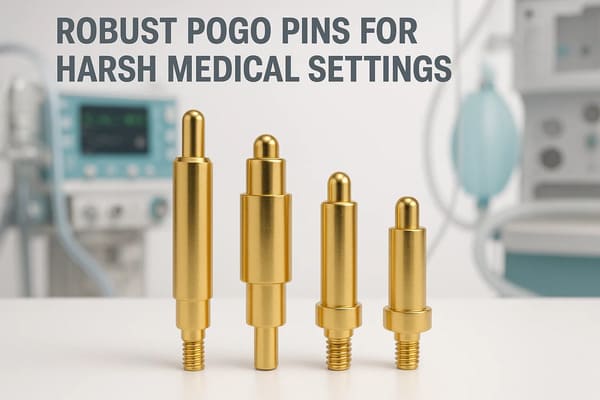
feedthrough, target, termination and device sealing architecture.
Mated and Unmated States Need Separate Review
| Connector State | Engineering Question |
|---|---|
| Fully Mated | Are required electrical and environmental conditions maintained? |
| Partially Mated | Can fluid or contamination reach energized contacts? |
| Unmated | Are contacts accessible to patients, users or conductive objects? |
| After Cleaning | Can residual liquid remain around the contact interface? |
| After Repeated Cleaning | Have seals, coatings or plastics changed? |
Priority 4: Separate Biological Safety from Connector Marketing
A connector should not be called biologically safe simply because it uses a
particular metal, gold finish or polymer.

Biological evaluation depends on how the finished device is used and which
materials can contact the patient directly or indirectly.
Medical-device developers should determine:
- whether the connector is patient contacting;
- which connector surfaces are accessible;
- the nature of the body contact;
- the duration of contact;
- which materials or processing residues are relevant;
- whether cleaning or aging changes the exposed material system.
ISO 10993-1 provides a risk-based framework for biological evaluation of
medical devices. It should not be reduced to a simple statement that one
connector material is universally “ISO 10993 compliant.”

Official reference:

    ISO 10993-1 — Biological evaluation of medical devices
.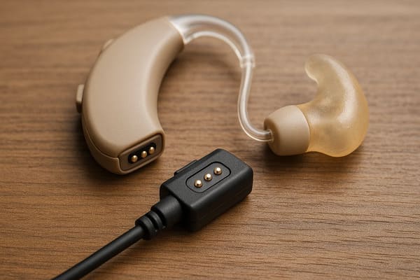
exposed surfaces, skin proximity, cleaning and repeated charging.
Gold Plating Does Not Automatically Establish Biocompatibility
Surface finish can affect electrical contact behavior and wear, but
biological safety cannot be inferred from a “gold-plated” description
alone.

The relevant evaluation may need to consider the complete exposed material
system, manufacturing process, contact duration and intended device use.
Priority 5: Design Retention and Breakaway Around Clinical Use
Magnetic connectors can be designed to release when a cable is pulled in a
defined direction.

This can be valuable in certain portable or bedside devices because less
mechanical cable load may be transferred into the equipment.

However, breakaway should not automatically be treated as a safety benefit
in every medical application.

If a connection is required for continuous monitoring, therapy or another
essential device function, unintended separation may create a different
hazard.| Use Scenario | Possible Design Priority |
|---|---|
| Charging Cable | Controlled release may be desirable |
| Portable Accessory | Balance retention with convenient removal |
| Wearable Module | Consider movement, clothing and accidental loads |
| Active Monitoring Interface | Unintended disconnection may require detection and alarm handling |
| Therapy-Related Connection | Retention and fault response require device-level risk analysis |
“Zero-Force Breakaway” Is Not an Accurate Engineering Term
A magnetic connection always requires some force to separate.The actual behavior depends on:
- magnet arrangement;
- seated retention;
- cable direction;
- axial versus peel loading;
- housing geometry;
- device mass;
- user interaction.
Capture force, seated retention and separation force should therefore be
treated as separate design requirements.
Priority 6: Protect Essential Electrical Performance at the System Level
Pogo pin spring compliance can help maintain contact with the intended
mating target, but the connector itself cannot ensure diagnostic
accuracy, uninterrupted patient data or essential device performance.
A complete signal path may include:
    Sensor / Module
    →
    Target
    →
    Pogo Pin
    →
    Connector Termination
    →
    PCB
    →
    Analog / Digital Front End
    →
    Processing System


Electrical performance can therefore depend on:- contact resistance and its variation;
- working stroke;
- contact layout;
- signal-return architecture;
- PCB routing;
- cable or FPC design;
- shielding where required;
- system fault detection.
Low Contact Resistance does not ensure Diagnostic Accuracy
A stable contact interface is useful, but diagnostic accuracy depends on the
complete measurement architecture.

A connector can introduce unwanted resistance or intermittency, but it
cannot independently create or supports accurate ECG, EEG, CGM, imaging or
other medical measurements.
Pin Count Does Not Prove Data Performance
More pogo pins provide more electrical paths, but they do not automatically
establish compatibility with a particular high-speed protocol.

Signal performance should be validated through the complete channel when
required.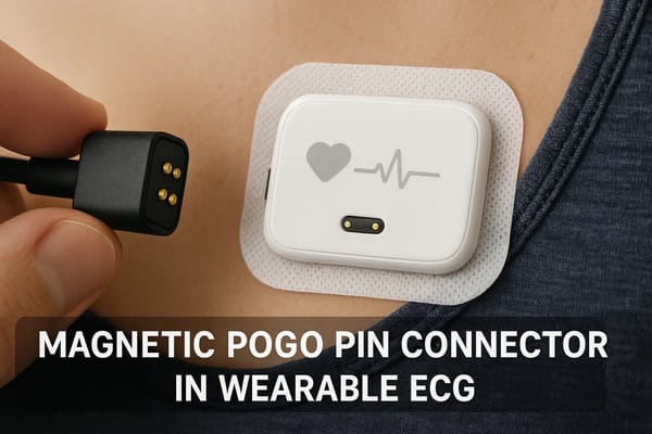
mechanical and environmental validation as part of the complete device.
Charging Capability Is Also a System Property
For rechargeable medical devices, the connector is only one element of the
power path.
A simplified path is:
    Charger
    →
    Cable / Dock
    →
    Magnetic Connector
    →
    Pogo Pin Contact
    →
    Device PCB
    →
    Charging Electronics
    →
    Battery


Voltage drop and heating depend on the complete electrical path.

Fast charging, battery management and charging safety should therefore not
be attributed to the magnetic connector alone.
Accessible Contacts Need an Empty-State Design
A flush magnetic charging interface may leave conductive contacts exposed
when the cable or dock is removed.
The medical-device team should consider:
- whether the contacts are energized while exposed;
- contact with conductive objects;
- cleaning liquids;
- sweat or skin oils;
- contact with the patient or operator;
- foreign-object bridging;
- power-enable logic.
Where appropriate, the system can separate physical attachment from
electrical power enable.
Magnets Introduce Their Own Medical-Device Design Questions
Permanent magnets provide useful capture and retention behavior, but their
presence should be considered in the complete device architecture.
Engineering review may include:
- nearby magnetic or position sensors;
- magnetically sensitive components;
- mechanical retention of the magnet inside the enclosure;
- temperature exposure;
- corrosion protection;
- metallic debris attraction;
- interaction with the intended use environment.
The correct assessment depends on the actual product and should not be
reduced to a universal magnet grade or force value.
Priority 7: Lifecycle Validation Must Reproduce Medical Use
A generic mating-cycle number does not establish medical-device service
life.

A useful endurance test should reproduce the important conditions of the
intended interface.
These may include:
- working stroke;
- mating target;
- mating and removal direction;
- electrical load;
- cleaning or disinfection cycles;
- moisture or sweat exposure;
- expected user handling;
- contact contamination;
- measurement intervals;
- defined electrical and mechanical failure criteria.
A connector tested for a high number of clean, unpowered laboratory cycles
should not automatically be assumed to achieve the same life after repeated
cleaning or powered use in a medical product.
Monitor Degradation, Not Just Final Failure
Connector degradation may appear gradually before complete electrical
failure.
Useful lifecycle observations can include:
- contact-resistance trend;
- intermittent connection events;
- spring-force change;
- working-stroke behavior;
- target wear;
- surface corrosion;
- magnetic retention;
- seal or housing degradation.
Medical Connector Qualification Should Include the Complete Contact Pair
The pogo pin and mating target wear together.

Testing only the spring contact while repeatedly replacing the mating target
may not represent a device in which the same target remains installed for
the complete service life.
Where Do Medical Standards Fit?
Medical-device standards and regulatory requirements apply according to the
finished device, intended use, market and manufacturer responsibilities.

A magnetic connector should not be represented as making the complete
product “FDA approved,” “IEC 60601 compliant,” “ISO 10993 compliant” or
“ISO 13485 compliant.”

Instead, the component supplier should provide the engineering and
manufacturing information needed by the medical-device manufacturer to
conduct the applicable device-level assessment.
ISO 10993-1: Biological Evaluation
ISO 10993-1 provides requirements and general principles for evaluating
biological safety within a risk-management process. Its relevance depends
on actual body contact and the complete material exposure of the device.

Official reference:

    ISO 10993-1
.
IEC 60601-1: Basic Safety and Essential Performance
IEC 60601-1 addresses general requirements for basic safety and essential
performance of medical electrical equipment. Depending on the product,
additional collateral or particular standards may also apply.

Official reference:

    IEC 60601-1
.
ISO 13485 and Quality Management
ISO 13485 defines quality-management-system requirements for organizations
involved in medical-device design, manufacture and related activities.
It is a quality-system framework rather than a performance certification for
an individual connector.

Official reference:

    ISO 13485:2016
.
U.S. FDA Quality Management System Regulation
For products placed on the U.S. medical-device market, applicable FDA
requirements should be determined by the finished-device manufacturer.
The FDA Quality Management System Regulation incorporates ISO 13485:2016
into the U.S. medical-device quality-system framework.

Official reference:

    FDA Quality Management System Regulation
.
Supplier Documentation Matters More Than “Medical Grade” Marketing
Medical-device engineering teams generally need controlled technical
information rather than broad performance claims.
Depending on the project, useful supplier documentation can include:
- approved drawings and revision control;
- material specifications where required;
- plating specifications where required;
- working-stroke definition;
- contact-force specification;
- electrical test conditions;
- critical dimensions;
- lot traceability;
- inspection records where contractually required;
- engineering change notification requirements;
- agreed qualification and validation data.
AOI Cannot Verify Every Medical Connector Requirement
Automated optical inspection can be valuable for visual and dimensional
characteristics that are accessible to the inspection system.

It does not by itself verify every relevant connector characteristic, such
as:- internal spring behavior;
- contact force at a defined stroke;
- contact resistance under the required condition;
- plating adhesion;
- long-term wear;
- temperature rise;
- cleaning compatibility;
- complete device environmental performance.
Inspection and process control should therefore be selected according to
the critical requirements of the approved design.
Medical Device Interface Selection Matrix
| Design Requirement | Engineering Question |
|---|---|
| Clinical / Operational Function | What happens if this connection is lost? |
| Pin Map | Which contacts carry power, return, detection or signals? |
| Working Stroke | What minimum, nominal and maximum compression is required? |
| Connection Detection | How does the device know the connector is fully seated? |
| Retention | How much normal handling load must the connector tolerate? |
| Breakaway | Is controlled release desirable or hazardous? |
| Patient Contact | Which materials can contact the patient and for how long? |
| Cleaning | Which agents and cleaning cycles will be used? |
| Sterilization | Is sterilization actually required, and by which validated process? |
| Environment | Will the interface see sweat, gel, liquids, dust or other contamination? |
| Electrical | What voltage, current and signal requirements apply? |
| Lifecycle | How many mating and cleaning cycles must the interface survive? |
| Traceability | Which component and process records are required by the project? |
Recommended Medical Connector Validation Plan
| Validation Area | Recommended Evaluation |
|---|---|
| Working Stroke | Verify minimum, nominal and maximum compression |
| Mating State | Evaluate fully seated, tilted and partially seated conditions |
| Connection Detection | Confirm the system distinguishes magnetic capture from valid connection |
| Retention / Release | Evaluate representative cable and accessory loads |
| Electrical Path | Measure voltage drop, resistance or signal behavior as required |
| Intermittency | Evaluate connection stability under representative handling |
| Cleaning Compatibility | Repeat the intended cleaning or disinfection process |
| Environmental Exposure | Evaluate applicable moisture, sweat, gel and contamination |
| Patient-Contact Materials | Evaluate according to the finished-device biological safety plan where applicable |
| Repeated Mating | Monitor wear, contact resistance and spring behavior |
| Post-Aging Function | Confirm connector performance after environmental and lifecycle exposure |
Information Required for a Medical Magnetic Connector Engineering Review
| Project Input | Information to Provide |
|---|---|
| Device Type | Wearable, monitor, charging device, diagnostic equipment or other medical application |
| Connector Function | Charging, sensor connection, accessory, signal, service or another function |
| Failure Consequence | What should the device do if the connection is interrupted? |
| Pin Map | Function of every electrical contact |
| Electrical Conditions | Voltage, continuous current, peak current and signal requirements |
| Working Stroke | Minimum, nominal and maximum pogo pin compression |
| Mating Geometry | Available X-Y-Z space, approach direction and mechanical datums |
| Retention / Breakaway | Required normal retention and desired separation behavior |
| Patient Contact | Direct, indirect or no contact and expected duration |
| Cleaning | Cleaning agents, concentration, temperature and expected cycles |
| Sterilization | Defined sterilization process if applicable |
| Environment | Moisture, sweat, gel, dust or other expected exposure |
| Lifecycle | Expected mating cycles and end-of-life criteria |
| Project Files | 2D drawing, 3D model, PCB layout and device assembly |
Frequently Asked Questions
What is a medical grade magnetic connector?
The term generally describes a magnetic connector intended for medical or
healthcare equipment, but it should not be treated as a standalone
certification. Suitability depends on the finished device, intended use,
patient contact, electrical requirements, cleaning process and validation.
Why are magnetic connectors used in medical devices?
They can support removable charging, accessory and sensor interfaces where
magnet-assisted mating, shallow contact surfaces or controlled breakaway
are useful to the product architecture.
Are medical magnetic connectors automatically biocompatible?
No. Biological safety depends on the actual patient-contacting materials,
processing, nature and duration of contact and the finished-device
biological evaluation.
Are medical magnetic connectors IP68 waterproof?
Not automatically. Environmental protection applies only to a defined and
tested connector or device assembly and can differ between mated and
unmated conditions.
Can medical magnetic connectors survive autoclave sterilization?
Only if the specific connector and complete assembly have been validated
for the defined sterilization process. Medical use alone does not establish
autoclave compatibility.
Can magnetic connectors supports medical signal accuracy?
No. The connector forms one part of the electrical channel. Diagnostic or
monitoring accuracy depends on the complete sensor, connector, PCB,
electronics, signal processing and device validation.
Are magnetic connectors safer because they break away?
Controlled breakaway can reduce cable load in some applications, but
unintended disconnection may be undesirable for connections required during
monitoring or therapy. The appropriate behavior depends on the device-level
risk analysis.
Does magnetic attachment mean the medical accessory is correctly connected?
Not necessarily. Magnetic capture can occur before all contacts reach their
required working position. Mechanical seating and electrical connection
state may need to be verified separately.
Does ISO 10993 certify a magnetic connector as biocompatible?
ISO 10993-1 provides a risk-based framework for biological evaluation of
medical devices. Applicability depends on the actual body-contact
conditions and material exposure of the finished device.
Does using an IEC 60601-compliant connector make the medical device IEC 60601 compliant?
No. IEC 60601 requirements apply to the relevant medical electrical
equipment or system. Connector design can support the device architecture,
but compliance must be evaluated at the applicable equipment level.
What information is needed for a custom medical magnetic connector?
Provide the medical-device function, Pin Map, voltage, current, signal
requirements, installation space, working stroke, connection criticality,
cleaning process, patient-contact conditions, lifecycle requirement and
device drawings.
Request a Medical Magnetic Connector Engineering Review
Explore

    custom magnetic connector solutions

for removable charging, accessory and device interfaces.

Review

    pogo pin and spring-contact solutions

for different contact layouts and mounting structures.

Learn more about CTP manufacturing and engineering capabilities on our

    About Us page
.

Submit the device function, Pin Map, electrical conditions, working stroke,
installation space, cleaning requirements and product drawings through the

    Get Quote & Samples page
.


    CTP can review connector geometry, pogo pin working stroke, mating
    targets, magnetic capture, seated retention, breakaway behavior and PCB,
    FPC, wire or cable termination for custom medical-device interface
    projects. Final biological safety, electrical safety, essential
    performance, cleaning compatibility, environmental protection and
    lifecycle must be evaluated within the complete medical-device
    architecture and applicable project-specific validation.
CTP ENGINEERING PATHS
Choose the right path for your project
Move from application requirements to a connector pair, a data-capable cable assembly, or a charging cable configuration. Final specifications are confirmed against an approved drawing and project validation plan.
Magnetic Connectors
Connector geometry, pin layout, mechanical integration and OEM/ODM review.
Engineering overview → 02Magnetic Data Cables
Power and signal allocation, cable exit, interface selection and assembly review.
Cable engineering → 03Magnetic Charging Cables
Browse the complete cable catalog and shortlist a starting structure for customization.
View cable catalog →