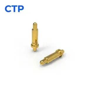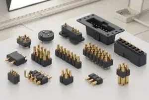
A good contact should fit into your product without dictating its shape. The board may sit below a shallow housing, a removable module may meet the device at a different level, or several contacts may need to share a small area. Our pogo pin range gives you different ways to make that connection.
A pogo pin working height drawing helps turn those choices into a part that fits. It shows where the contact sits when the product is connected, so the spring has room to work within the space available. With CTP, you can explore surface-mount pins, through-hole contacts, integrated arrays and double-ended designs around that installed position.
Spring contacts make room for a removable connection
A pogo pin uses a moving plunger inside a small body. As the mating surface approaches, the plunger compresses and applies contact pressure. That movement is useful where two parts need to connect without a permanently attached wire between them, such as a removable accessory, a docked instrument or a module inside a device.
Our individual contacts let you place each connection where the product needs it. You might need two separated contact points beside a housing feature, or a small group arranged around another component. An individual pin gives the board designer more freedom over that layout than a fixed multi-contact block.
The benefit is practical: the electrical interface can follow the product’s arrangement. A spring contact also provides movement along its contact axis, which helps accommodate the intended mating action. The surrounding housing establishes the final seated position, leaving the contact to do its electrical job.
A surface-mount base keeps the PCB connection on the board surface
Our vertical SMT pogo pin, CTP-PP-SMT-A01, has a circular mounting base in place of a long through-hole tail. It is a straightforward option when your PCB layout calls for a surface-mounted contact facing toward a mating pad above the board.
The circular SMT base suits individually placed contact points
For a compact desk accessory, two or more of these pins could sit beside other components rather than occupying one long connector opening. The layout can reflect the available space and the location of the matching targets. That is particularly helpful when the contact area is only one small part of the product’s external design.
The base, PCB land and spring-loaded tip each have a clear role. The base supports the board connection, while the tip meets the mating surface. Reviewing them together gives the designer a sensible starting point for a tidy interface, without introducing a through-hole tail where the board layout calls for surface mounting.
Height still matters. The drawing connects the board surface to the position of the mating target when the accessory is seated. Getting that relationship clear early lets the enclosure and PCB develop around the same contact arrangement, instead of trying to reconcile two different installed heights later.
Through-hole pins offer a different route into the board
The CTP through-hole spring-loaded pogo pin, CTP-PP-TH-A01, uses a cylindrical body and a straight mounting tail. It suits a board design built around a through-hole connection, with the working contact extending toward its target on the other side of the assembly.
This gives you another way to arrange the contact within the device. A product with room for a straight tail beneath the board may be well suited to this format. The choice can follow your board construction, assembly approach and internal space, rather than a preference for one mounting style in every product.
A shouldered body adds a useful geometric feature
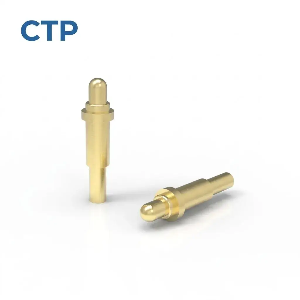
Our shouldered DIP contact, CTP-PP-DIP-A02, has a stepped body with a radial shoulder near the plunger end and a narrower straight tail. That visible change in shape gives the mechanical designer another feature to consider when developing the surrounding installation.
The shoulder’s exact locating or retaining role is defined in the selected drawing. Its appeal is the availability of a different body geometry when a plain cylinder does not suit the arrangement. You can compare the contact’s shape with the board, support and housing as one assembled connection.
Several contacts can arrive as one integrated array
If your product needs a group of connections in a regular pattern, an array can be more convenient than arranging individual pins. Our ten-contact dual-row SMT connector, CTP-PC-10P-DR-A01, holds ten spring contacts in a five-by-two housing.
The housing brings the contact positions together in one part. That makes it easier to discuss the connector’s location on the PCB and the matching target area as a single interface. For a removable control module, the two-row arrangement can provide several assigned electrical paths without spreading them along one long edge.
Each pin still has its own spring movement. The integrated housing establishes the contact pattern; the product’s seating arrangement establishes how the array meets its targets. It is a useful combination when you want a coordinated group of contact points with compliance at each position.
The working height drawing is especially valuable here because the complete array shares one installed relationship to the mating part. The board designer, enclosure designer and person choosing the mating targets can see the same layout and seated condition.
Double-ended contacts can bridge two facing surfaces
Some connections are better approached from both ends of the contact. Our long-plunger double-ended pogo pin, CTP-PP-1P-DE-A02, has contact interfaces at both ends, with visibly different reach on the two sides.
Unequal contact ends can suit different interface depths
Imagine a small module whose target sits inside a recess, opposite a shallower board-side contact. An extended contact end is a geometry worth exploring for that arrangement. It gives you another route to the target rather than forcing both sides to use the same exposed shape.
A double-ended pin remains one electrical path. Its available movement at each end and its retention in the device are defined for the chosen part. The benefit is the two-sided contact format itself: it can connect facing conductive surfaces within a product-specific compression arrangement.
That can be appealing where the module should remain separable from the main assembly. The pin, its carrier and the two target surfaces can be developed together, with the drawing showing how the completed stack fits. The longer visible end helps with reach; the drawing establishes the working position.
A clear working height drawing keeps the product easy to understand
There is also a useful distinction between reach and the amount a contact moves. A tall body may help a pin reach a target positioned above the board, while a different base may suit the mounting surface below it. Looking at the complete profile lets you choose a sensible starting geometry without assuming that the tallest visible pin has the most usable travel.
For a handheld instrument with a detachable sensing head, that can simplify the layout conversation. The team can place the main board where it suits the electronics, then compare a straight-tail pin with a longer-reach or two-sided contact. The connection becomes part of the product arrangement rather than a reason to move every other component.
A group of contacts may call for a different answer. If the instrument needs ten neighboring paths, the five-by-two SMT array brings them together in a defined housing. If it needs only a few widely spaced points, separate contacts can follow those locations. Our range gives you both routes, so the contact format can follow the device rather than the other way around.
These choices also make the finished interface easier to explain. The product drawing can show one recognizable contact style, its mounting feature and the mating surface it serves. That clarity is useful from the first physical layout through the selection of the corresponding parts for a repeat build.
The free height is the contact’s uncompressed position. The working height is its position in the connected product. Keeping those two conditions distinct makes a product drawing easier to use, especially when comparing SMT, DIP and double-ended formats with different mounting features.
For your device, the most useful drawing shows the board reference, the selected contact and the target in the seated position. It can also show the housing feature that stops further movement. You do not need a page of calculations to explain the basic relationship; a clear assembled view often makes the choice easier to discuss.
Our guide to pogo pin types offers another way to compare the mounting formats. If you are still arranging the product, start with the contact locations and the space between the two mating parts. Those details usually make the useful options much clearer.
A compact SMT base, a straight through-hole tail, a shouldered body or a two-sided contact can each solve a different packaging problem. The right choice is the one that fits naturally into your product and gives the mating surfaces the contact movement they need. A well-defined working height drawing helps you make that choice with the complete device in view.