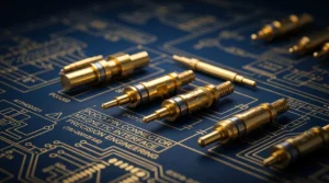
A removable module does not always need a wire soldered to each side of its connection. A double-ended pogo pin gives two facing conductive surfaces another way to meet: one small contact component with an electrical interface at both ends.
Our double-ended range includes a straight two-sided format, a rounded-tip design and a version with an extended plunger at one end. These shapes give you different starting points for the space between the module and the main device. Double ended pogo pin compression is then defined around the two mating surfaces and the way the assembled product holds them together.
Two contact ends form one electrical bridge
The CTP double-head spring contact, CTP-PP-1P-DE-A01, is an individual component with contact interfaces at both ends. It provides one electrical path through the part, rather than two independent circuits.
This format can be considered for a product with a removable board, an interchangeable module or another pair of facing contact surfaces. The connection is developed as a compression interface, with the product structure locating the parts and the contact completing the electrical path.
The two-sided format can suit a separable module stack
Imagine a compact module held above the main board by a carrier. Its target faces downward, while the board target faces upward. A double-ended contact can be evaluated between those surfaces, allowing the electrical connection to be part of the module’s installed position.
The appeal is the arrangement itself. The module can remain separable at that interface without making a permanently attached wire the starting point for the design. The carrier, targets and contact are considered together so the connection fits the intended assembly.
The exact movement available at either end comes from the selected drawing. A two-ended appearance does not establish two equal internal springs. What the format gives you is a compact two-sided contact to develop around the product’s actual target positions.
A rounded-tip version offers a straightforward contact profile
Our rounded-tip double-ended pogo pin, CTP-PP-1P-DE-A03, has rounded contact geometry on both sides of a straight cylindrical body. Its visible form makes the two target relationships easy to picture in the assembly.
Rounded ends can be evaluated against smooth mating targets
For a module with facing conductive pads, the rounded-end design offers a clear geometry to compare with the target area. The contact profile, intended pressure and normal mating movement can be considered together. The surrounding housing establishes the final position of the two surfaces.
That can help a product team keep the interface discreet. The electrical bridge sits within the carrier or enclosure, while the user handles the removable module as a complete part. The spring-contact choice supports the product’s separation point without becoming a prominent external connector.
The rounded format is one option within the range, not a universal answer for every target finish. Its value is the available two-sided profile. It can be compared directly with the contact surfaces your device uses, instead of selecting a tip based only on its appearance in isolation.
A longer plunger can reach a target at a different depth
The CTP long-plunger double-ended contact, CTP-PP-1P-DE-A02, has visibly unequal contact-end geometry. One side extends farther than the other, giving the designer another option where the two targets do not sit at similar depths.
Unequal reach can follow a recessed module contact
A replaceable sensing module might have a target set back inside its housing, opposite a more accessible board-side target. The extended-end contact is worth comparing in that arrangement. It offers a different reach without requiring the two target surfaces to be redesigned as if they were identical.
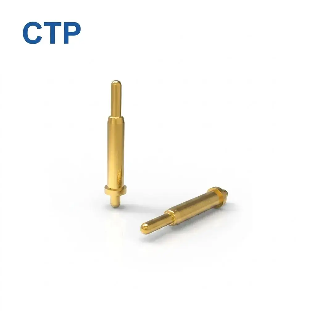
This is particularly helpful while the module’s carrier and housing are still being arranged. The contact can be selected with the recess depth and board position in view. The longer visible end addresses reach; the selected drawing defines its working movement within the completed interface.
The distinction matters because a long-looking contact is not automatically a long-travel contact. Choosing it for the geometry it actually provides keeps the design conversation clear. The benefit remains tangible: another component shape that can fit a product with different target positions on its two sides.
Double ended pogo pin compression belongs to the complete assembly
Compression is the movement from the free position to the operating position. In a double-ended arrangement, both target surfaces and the way the contact is held influence that relationship. The useful drawing shows the contact within the carrier, between the two surfaces it connects.
For a removable electronics module, this keeps the interface aligned with the product’s assembly. The housing or guides establish where the module sits, while the contact works within that position. The pin is an electrical component within the stack, rather than the main structural stop for the whole module.
This division of roles can make the finished product easier to use. The module has a defined position and attachment action. The contact bridge then supports the electrical connection inside that action, without requiring a separate user operation at each contact end.
The pogo pin types guide compares the broader contact families. A two-sided contact is most attractive when the two-facing-surface arrangement fits the product. Other mounting formats remain valuable where one side should have a fixed PCB termination.
A one-sided PCB contact may suit a different part of the same device
Our through-hole pogo pin, CTP-PP-TH-A01, has a straight mounting tail for the board and a spring-loaded tip for the mating target. It provides a different connection route when the contact should remain attached to one PCB.
For a charging cradle, that may be the simpler arrangement: the board-mounted contacts stay in the cradle while the device’s targets meet them during placement. The removable interface exists at the tips, with the tails forming the permanent board connection.
The individual SMT/SMD pogo contact, CTP-PP-1P-A01, offers another route for a surface-mount board layout. It can be placed independently where the device needs one or a few separated electrical points.
Having these options alongside the double-ended range helps the connection follow the design. The same product may use board-mounted contacts at an external dock and a different two-sided arrangement inside a removable module. The useful feature is the appropriate contact architecture for each location.
A two-sided interface can fit neatly into a modular product
There is a useful packaging difference between bringing a wire to a module and bringing the module to a contact. A wire needs its own route and connection point. A compression interface can be considered where the module already has a defined installed position and facing targets. The better approach depends on the space and service action of the product.
For a shallow module carrier, the straight cylindrical double-ended format provides a simple profile to review. If one target lies deeper inside the removable part, the extended-plunger design brings a different reach to the discussion. If the visible contact geometry on both sides is important, the rounded-tip version gives the team that specific form to compare.
This variety helps the electrical interface follow the mechanical arrangement. The device does not have to treat two facing targets as if they were a standard cable socket. The contact and carrier can instead be developed around the surfaces that are already part of the module concept.
It also keeps the component’s role easy to describe. One end meets the first target, the other meets the second, and the complete part forms the assigned electrical path. The surrounding structure provides the positioning that allows those two contacts to work as intended.
Modular devices create more than one packaging challenge. The main board needs a sensible position, the removable part needs support, and the electrical path has to meet both. A small two-sided contact gives the team another way to bring those needs together.
For an equipment maker, that can mean preserving the module’s useful shape while comparing the contact geometry within its carrier. The rounded-end and long-plunger versions offer different profiles, so the choice can reflect the actual target surfaces rather than one assumed interface depth.
The number of electrical paths is then built from the required contacts. Each double-ended component remains one path, and its spacing belongs to the complete design. A group of them can be considered around the module’s target pattern where the carrier provides the necessary positioning.
The right starting point is a view of the two surfaces you want to connect. If their arrangement suits a compression bridge, our double-ended formats offer several practical shapes to explore. The product can then be developed around a connection that fits its own module, carrier and board.