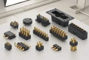
A magnetic pogo pin interface can provide removable power, detection and project-specific communication between a consumer device and an accessory module. It does not independently create modularity, zero latency, USB compatibility, uninterrupted power, corrosion immunity or an IP rating. The complete design must coordinate the mechanical load path, contact working stroke, magnetic capture, target geometry, Pin Map, power control, communication protocol, environmental exposure and product-level validation.
Modular consumer electronics allow one host device to connect with removable keyboards, charging stands, display modules, control surfaces, battery packs, sensor accessories or service components.A magnetic pogo pin interface can simplify the final attachment movement by combining spring-loaded electrical contacts with magnet-assisted positioning or retention.
However, a successful modular product requires more than a connector. The host and accessory must also agree on:- Mechanical support and orientation
- Electrical power limits
- Accessory detection and identification
- Communication protocol
- Software compatibility
- Fault handling
- User feedback
- Environmental and durability requirements
The connector should therefore be treated as one subsystem inside a larger modular architecture.
What Makes a Consumer Electronics Product Modular?
A product is not modular merely because two parts can be separated.

A practical module normally has a defined:- Mechanical interface
- Electrical interface
- Communication interface
- Power budget
- Identification method
- Supported operating state
- Replacement or upgrade process
- Compatibility policy
| Modular Function | Primary System Element | Connector Contribution |
|---|---|---|
| Physical attachment | Housing, guides, latches, magnets and mechanical stops | Provides electrical connection after the approved position is reached |
| Power delivery | Host power-management circuit and accessory load | Provides part of the conductive path |
| Accessory detection | Host and accessory detection circuits | May provide a presence or identification contact |
| Data communication | Transceivers, firmware, protocol and operating system | Must preserve the required physical electrical channel |
| Compatibility | Mechanical coding, firmware and product ecosystem | Can support physical coding or identification contacts |
| Fault protection | Current limiting, power switches, ESD and system software | Must remain safe during partial mating and contamination |
Magnets attach or guide the module. Pogo pins provide compliant electrical contacts. The host electronics and firmware determine what the attached module is allowed to do.
Choose the Interface Architecture Before Choosing the Pin Count
Magnetic pogo pins are one of several possible modular interface architectures.| Interface Architecture | Possible Advantage | Primary Trade-Off |
|---|---|---|
| Magnetic pogo pin interface | Custom geometry, guided attachment and no conventional plug insertion | Proprietary accessory, exposed contacts and project-specific validation |
| Non-magnetic pogo pin interface | Compliant contact where the mechanical structure already provides location | Requires an independent latch, clamp or docking structure |
| USB-C | Standardized power, data and broad accessory availability | Requires a defined receptacle and plug insertion |
| Board-to-board connector | Dense internal connection for assembled modules | Usually not intended for frequent consumer removal |
| FPC or wire harness | Continuous internal connection between subassemblies | Not a quick-release modular interface |
| Contactless power and wireless data | No exposed conductive mating contacts | Requires separate power-transfer and communication systems |
| Rotary connector or slip-ring architecture | Can support continuous relative rotation | Introduces wear, electrical noise and specialized mechanical requirements |
The decision should be made from the actual product requirements rather than from the appearance of a preferred connector.Define the Module Supply Scope
Before developing the connector, define what the supplier is expected to deliver.| Supply Scope | Included Elements |
|---|---|
| Individual pogo pins | Separate spring-loaded contacts installed by the customer |
| Pogo pin connector assembly | Several contacts positioned in one insulating housing |
| Magnetic connector pair | Pogo pins, targets, magnets and mating housings |
| Magnetic cable assembly | Connector head, cable, strain relief and opposite-end termination |
| Accessory subassembly | Connector, PCB, protection circuit and mechanical housing |
| Complete modular accessory | Finished functional module with electronics, firmware and enclosure |
A connector manufacturer may support the contact and mechanical interface without being responsible for the complete accessory firmware, protocol qualification or host-device certification.Separate the Structural Load Path from the Electrical Contacts
A removable screen, keyboard, battery module or control accessory may apply weight, bending moment, vibration and user force to the host device.

The pogo pins and their solder joints should not carry the complete module load.
A preferred load path is:
Accessory → Support Surfaces or Latch → Host Housing → Product Structurerather than:
Accessory → Magnets → Pogo Pins → Solder Joints → Host PCBThe mechanical architecture should consider:
- Module mass
- Center of gravity
- Normal use direction
- Vibration and shock
- Cable pull where present
- Accidental twisting
- One-handed installation and removal
- Drop conditions
- Housing deformation
- Long-term latch or magnet wear
Magnets may provide capture or retention, but mechanical surfaces should establish the final position and carry the primary structural load.Magnetic Capture and Mechanical Alignment Are Different Functions
Magnetic attraction can guide an accessory toward the host, but it does not automatically define the final electrical alignment.Possible mechanical locating features include:
- Asymmetric housing geometry
- Locating ribs
- Recesses and bosses
- Alignment pins
- Side walls
- Keyed target spacing
- Mechanical latches
- Hard stops
Final connector performance depends on the complete tolerance stack, not a fixed magnetic-force value.

Excessive magnetic attraction may increase:- Seating impact
- Pogo pin over-compression
- User-removal effort
- Housing stress
- Attraction of ferromagnetic particles
- Interaction with magnetic sensors, speakers or internal magnets
Capture force, seated retention and removal force should be treated as separate requirements.Control the Pogo Pin Working Stroke
Working stroke is the actual compression applied to the pogo pins after the accessory reaches its final installed position.A simplified calculation is:
S = Hfree - Hseatedwhere:
- S is the applied compression
- Hfree is the installed free contact height
- Hseated is the final distance between the contact mounting plane and mating target
The tolerance stack may include:
- Pogo pin free-height tolerance
- PCB mounting position
- Housing dimensions
- Target position and flatness
- Mechanical-stop position
- Module deformation
- Latch wear
- Magnet position
- Surface coating thickness
- Debris trapped at the interface
| Stroke Condition | Possible Result |
|---|---|
| Below the approved minimum | Intermittent power, unstable detection or communication failure |
| Within the approved range | Intended contact force and electrical state |
| Above the approved maximum | Spring bottoming, target damage, housing load or PCB stress |
| Unequal compression | Different contact resistance and uneven current distribution |
Magnets should not force the pogo pins into uncontrolled maximum travel.Treat Partial Mating as a Real System State
A module may be magnetically attached without being electrically seated.| Partial-Mating Condition | Possible Risk | Required Review |
|---|---|---|
| One side attaches first | Unexpected contact sequence | Approach geometry and first-contact location |
| One pogo pin touches first | Power is present without the intended return or detection state | Pin-height and target-position tolerance |
| Module is laterally offset | A contact reaches an adjacent target | Target spacing and maximum credible offset |
| Magnetically retained but not seated | False accessory-recognition or charging indication | Independent electrical seating verification |
| Incorrect accessory is attached | Wrong voltage, polarity or protocol | Mechanical and electrical identification |
| Conductive debris bridges contacts | Short circuit or localized heating | Power control and foreign-object protection |
| Module is removed under load | Arcing, transient behaviour or communication interruption | Removal detection and power sequencing |
Develop the Pin Map from Actual Module Functions
Three, five or seven contacts do not define the capability of a modular interface.| Possible Function | Engineering Question |
|---|---|
| Power | What voltage, continuous current and peak current are required? |
| Power return | What return path exists during every credible attachment state? |
| Accessory detection | Does the signal indicate initial presence or verified full seating? |
| Accessory identification | Must the host identify accessory type, revision or capability? |
| Power enable | What condition authorizes the host to energize the contacts? |
| Low-speed communication | What voltage levels, protocol and pull-up structure apply? |
| High-speed communication | What physical layer, lane count and channel requirements apply? |
| Temperature or fault signal | Where is the condition measured and how is it reported? |
| Service or diagnostics | Is factory programming or field diagnostics required? |
| Shield or chassis | How is it related to signal return and the product enclosure? |
Power return, signal return, shield and chassis should not automatically be treated as the same electrical node.Redundant Contacts Do Not Automatically Create Redundant Operation
Two or more contacts may be connected in parallel for current capacity or fault tolerance, but parallel pins do not ensure uninterrupted operation.Current sharing can vary because of:
- Different working strokes
- Target tilt
- Contact-resistance variation
- PCB routing differences
- Termination variation
- Contamination on one target
- Plating wear
A simplified current-sharing model for two parallel contacts is:

I1 / I2 = R2 / R1

The lower-resistance contact may carry more current and experience higher local heating.

True N+1 redundancy requires:- Independent current or signal paths
- Fault detection
- Isolation of the failed channel
- Sufficient remaining capacity
- System-level recovery logic
Simply adding one extra pogo pin is not sufficient.Evaluate the Complete Power Path
The module power path may include:
- Host battery or external power source
- Host power-management circuit
- Protection and power switch
- Host PCB routing
- Host contact
- Pogo pin interface
- Accessory target and PCB routing
- Accessory regulator or charging circuit
- Accessory load or battery
A simplified channel model is:
Rpath = Rhost + Rtermination1 + Rpogo + Rinterface + Rtarget + RaccessoryThe voltage drop is:
Vdrop = I × RpathThe resistive loss is:
Ploss = I² × RpathDefine:
- Operating voltage
- Continuous current
- Peak current and duration
- Inrush current
- Permitted voltage drop
- Permitted temperature rise
- Short-circuit response
- Reverse-polarity condition
- Power enable and disable sequence
- Behaviour during removal
A connector should not be described as “fast charging” until the complete power source, load, thermal path and charging controller have been defined.Pin Count Does Not Prove USB or DisplayPort Capability
A five-pin or seven-pin array may contain enough conductors for a proposed channel, but conductor count does not establish protocol compatibility.High-speed communication may require control of:
- Differential impedance
- Insertion loss
- Return loss
- Near-end crosstalk
- Far-end crosstalk
- Skew
- Mode conversion
- Reference-plane continuity
- Connector parasitic inductance and capacitance
- PCB and cable routing
- ESD protection
- Protocol enumeration
- Interoperability
The complete channel should be modelled and tested from the host transmitter to the accessory receiver.

Low DC contact resistance does not establish USB 3.x, DisplayPort or another high-speed physical layer.
Signal Return and EMI Require System-Level Design
Additional ground contacts may improve the return environment in a specific layout, but they cannot independently eliminate EMI or crosstalk.Review:
- Signal and return-pin arrangement
- Reference-plane continuity
- Host and accessory PCB stack-up
- Connector transition geometry
- Nearby antennas
- Housing metal
- Shield connection
- Common-mode current paths
- Module installation position
- Radiated and conducted behaviour
A metal connector frame should not automatically be described as a complete Faraday cage.Standard Pogo Pins Do Not Provide Continuous 360-Degree Rotation
A normal pogo pin interface is designed around a defined target and compression direction.

A module that rotates continuously may require:- Concentric ring targets
- A slip-ring structure
- Rotary contacts
- Rolling contacts
- Angle-limited flexible circuits
- Contactless power and wireless data
Allowing a standard pogo pin to scrape around a circular target may produce:- Side load
- Target wear
- Metallic debris
- Contact-resistance variation
- Plunger sticking
- Signal interruption
“360-degree flexibility” should only be used when the actual rotary electrical architecture has been developed and validated.Typical Modular Consumer Electronics Applications
| Application | Possible Interface Role | Primary Design Focus |
|---|---|---|
| Detachable tablet keyboard | Accessory power, detection and project-specific data | Tablet support, working stroke and host power budget |
| Charging or desktop stand | Power, detection and optional accessory functions | Mechanical support, exposed-contact state and thermal behaviour |
| Detachable smart display base | Power and communication between display and base | Display mass, center of gravity and removal under power |
| Gaming accessory module | Charging, control input or accessory identification | User impact, vibration and magnetic-sensitive controls |
| Camera or sensor module | Power, trigger, identification and project-specific data | Alignment, optical position and high-speed channel requirements |
| Replaceable battery module | Power, temperature, identification and status | Current, inrush, sequence, latching and battery safety |
| Smart-home control module | Power and control between removable interface components | Installation errors, cleaning and long-term contact stability |
| Service or production module | Programming, diagnostics or calibration | Security, fixture life and controlled access |
These products should not share one universal magnetic force, Pin Map, current rating or communication protocol.External Contacts Require a Safe Electrical State
Exposed contact arrays may be touched by users or conductive objects when no accessory is installed.Foreseeable contact may include:
- Coins
- Keys
- Metal tools
- Jewellery
- Moisture
- Cleaning cloths
- Incorrect accessories
- Metallic particles attracted by magnets
Possible controls include:
- Normally de-energized contacts
- Current limiting
- Accessory detection before power enable
- Accessory identification
- Recessed targets
- Insulating barriers
- Mechanical coding
- Short-circuit shutdown
- Transient and ESD protection
- Fault indication
Environmental Reliability Depends on the Complete Contact Pair
Consumer electronics interfaces may encounter:| Exposure | Possible Effect | Required Design Input |
|---|---|---|
| Hand oils | Surface film and dust retention | Target position and cleaning method |
| Perspiration | Electrolytic residue, leakage and corrosion | Expected body contact and charging condition |
| Dust and fibres | Blocked plunger movement or incomplete seating | Storage environment and recess geometry |
| Drink or cleaning residue | Electrical bridging, corrosion or sticky movement | Approved cleaning process and fault protection |
| Metallic particles | Accumulation near magnets and target bridging | Magnetic layout and inspection access |
| Repeated vibration | Fretting, wear and contact-resistance variation | Module retention and vibration environment |
The plunger finish and mating-target finish should be selected and tested as one contact pair.

A fixed nickel, palladium-alloy and gold stack should not be copied into every consumer-electronics interface without reviewing the actual substrate, target, wear and environment.
Ingress Protection Belongs to the Complete Enclosure
Flush conductive targets may remove the need for a deep receptacle in some products, but they do not automatically establish IP68 or hermetic sealing.The protection boundary may include:
- Target inserts
- Insert-molded joints
- Adhesives or potting
- Housing seams
- Buttons
- Speakers and microphones
- Sensor windows
- Battery doors
- Internal terminations
Any IP classification should identify the tested complete enclosure, product state and test method.

LCP housing material, insert molding or gold plating does not independently create an IP68 or hermetic result.
Module Replacement Does Not Automatically Create Repairability
A physically removable module may still be restricted by:- Firmware compatibility
- Serialization
- Calibration requirements
- Security authentication
- Adhesives or surrounding assembly steps
- Unavailable replacement parts
- Product warranty policy
A repairable modular ecosystem should define:- Which modules are user-replaceable
- Which modules require authorized service
- How compatibility is confirmed
- Whether calibration is required
- How replacement parts are supplied
- How failed modules are diagnosed
- How software handles module revisions
Recommended Development Sequence
- Define the host device and removable module.
- Define the mechanical and electrical supply scope.
- Define the module mass, support surfaces and removal direction.
- Complete the Pin Map.
- Define voltage, current, inrush and temperature-rise limits.
- Define the communication physical layer and data rate.
- Calculate minimum, nominal and maximum working stroke.
- Define magnetic capture, retention and release requirements.
- Review partial-mating and wrong-accessory states.
- Define target materials, plating and cleaning access.
- Develop power-control and accessory-identification logic.
- Build production-intent host and accessory prototypes.
- Validate the complete modular system.
Recommended Validation Plan
| Requirement | Possible Evaluation |
|---|---|
| Mechanical architecture | Host, module, support surfaces, latch, magnets and load-path review |
| Working stroke | Minimum, nominal and maximum pogo pin compression |
| Target alignment | Lateral, angular, height and manufacturing-tolerance envelope |
| Magnetic capture | Approach, seating impact, retention and user removal |
| Partial mating | Offset, tilted, one-contact-first and retained-but-unseated states |
| Wrong accessory | Mechanical fit, identification, voltage and protocol response |
| Contact resistance | Defined test current, stroke, target and environmental condition |
| Power path | Voltage drop, inrush and temperature rise |
| Parallel contacts | Individual current and temperature distribution |
| Power sequencing | Detection, identification, enable, removal and recovery |
| Short circuit | Conductive objects, contamination and adjacent-target bridging |
| ESD | Exposed contacts and surrounding enclosure |
| Low-speed data | Protocol operation, interruption and reconnection recovery |
| High-speed data | S-parameters, loss, crosstalk, eye performance and interoperability |
| EMI and wireless operation | Complete powered product with all supported modules |
| Vibration and shock | Electrical continuity and mechanical retention |
| Repeated attachment | Project-defined cycles with electrical and visual inspection |
| Powered attachment | Repeated engagement and separation under the intended electrical state |
| Contamination | Oil, dust, moisture, cleaning residue and metallic particles |
| Enclosure protection | Complete host and accessory in their defined product states |
| Software compatibility | Supported, unsupported and revised accessory modules |
| Production variation | Minimum and maximum assembled tolerances and process capability |
Information Required for an Engineering Review
| Requirement Group | Information to Provide |
|---|---|
| Host product | Tablet, display, camera, controller, smart-home device or another product |
| Accessory module | Keyboard, stand, battery, control module, sensor or another accessory |
| Supply scope | Individual pins, connector pair, cable assembly or complete subassembly |
| Mechanical geometry | 3D models, module mass, center of gravity, support and removal direction |
| Contact area | Available length, width, depth, pitch and restricted regions |
| Pin Map | Power, return, detection, identification, data, shield and service functions |
| Electrical conditions | Voltage, continuous current, peak current and permitted voltage drop |
| Thermal conditions | Ambient temperature and permitted interface temperature rise |
| Communication | Proprietary low-speed, USB, DisplayPort or another physical layer |
| Working stroke | Minimum, nominal and maximum compression |
| Contact force | Required force at defined stroke positions |
| Magnetic behaviour | Capture, retention, removal, polarity and restricted magnet zones |
| Target contacts | Dimensions, material, finish, flatness and mechanical support |
| Environment | Dust, oils, moisture, vibration, cleaning and expected location |
| Compatibility | Supported module families, revisions and identification requirements |
| Durability | Attachment frequency, electrical load and acceptance criteria |
| Files | 2D drawings, 3D models, schematics, PCB layout and module assembly |
| Commercial | Prototype quantity, production forecast and development stage |
Common Engineering Mistakes
| Mistake | Possible Consequence | Better Approach |
|---|---|---|
| Calling magnetic connectors a modular revolution | The software, mechanical and ecosystem requirements are ignored | Present the connector as one modular-interface option |
| Calling the interface wireless | The conductive charging or data path is described incorrectly | Use magnetic contact interface or conductive magnetic connector |
| Using magnets as the only locator | Partial seating and unequal pogo pin compression | Use mechanical guides and hard stops |
| Allowing contacts to carry module weight | Pin, target, PCB or solder-joint damage | Provide an independent structural load path |
| Assigning N+1 redundancy by adding one contact | No fault detection or channel isolation exists | Develop complete electrical and software redundancy |
| Assuming parallel pins share current equally | One contact may overheat | Measure individual current and temperature |
| Assigning USB 3.x by Pin count | The physical channel may fail loss, impedance or crosstalk limits | Validate the complete channel and protocol |
| Claiming zero latency | Firmware, protocol and system processing are ignored | Measure complete end-to-end response |
| Claiming 360-degree rotation | A normal pogo pin experiences uncontrolled sliding and wear | Use a purpose-designed rotary architecture |
| Publishing a universal magnetic force | The value does not match module mass, air gap or removal direction | Measure the complete assembled product |
| Using one plating stack for every product | The finish does not match the target, movement or environment | Validate the complete contact pair |
| Calling the connector IP68 or hermetic | The complete enclosure boundary is ignored | Test the defined final assembly |
| Publishing ±0.01 mm without a measurement definition | The production capability cannot be verified | Define the feature, datum, gauge and process capability |
Engineering Reference Sources
Final standards, protocol versions and acceptance criteria should be confirmed for the actual host, accessory and target market.-
Apple — Smart Connector providing power and data to a detachable keyboard
-
Microsoft — Magnetically attached Surface Type Cover
-
USB-IF — USB 3.2 electrical, link and interoperability testing
-
IEC 60512-28-100:2024 — Connector signal-integrity tests
-
IEC 60512-2-2 — Contact-resistance measurement
-
IEC 60512-9-1 — Mechanical operation endurance without electrical load
-
IEC 60512-9-3 — Mechanical operation with electrical load
-
IEC 60529 — Degrees of protection provided by enclosures
-
AMPP — Definition and conditions of galvanic corrosion
Frequently Asked Questions
Do magnetic pogo pins make a product modular?
Not by themselves. A modular product also requires mechanical support, electrical definition, accessory identification, software compatibility and a replacement strategy.Are magnetic pogo pin interfaces wireless?
No. Electrical power or data passes through conductive contacts. Magnets only assist positioning or retention.Can magnetic pogo pins replace USB-C?
They may replace routine plug insertion in a proprietary accessory system, but they do not automatically provide standardized USB power, data or accessory interoperability.Does a five-pin or seven-pin connector support USB 3.x?
Not automatically. USB 3.x requires the correct physical channel, differential routing, protection, protocol implementation and compliance testing.Can extra pogo pins provide N+1 redundancy?
Only when the electrical system can detect and isolate a failed channel while the remaining contacts retain sufficient capacity.Do parallel power contacts share current equally?
Not necessarily. Differences in compression, resistance, contamination and PCB routing can cause unequal current distribution.Do magnets supports correct alignment?
No. Magnets assist capture. Final alignment and contact compression should be controlled by mechanical guides and stops.Can a standard pogo pin interface rotate through 360 degrees?
Not as a normal axial contact. Continuous rotation requires a dedicated rotary-contact, slip-ring or contactless architecture.Can a magnetic connector automatically achieve IP68?
No. An IP rating applies to a defined and tested enclosure assembly.What information is required for a modular connector review?
Provide the host and accessory models, supply scope, mechanical geometry, Pin Map, electrical conditions, communication protocol, stroke, magnetic requirements, environment and available drawings.Prepare Your Modular Electronics Interface Project
Review

    individual pogo pin structures

when the product requires separately integrated spring-loaded contacts.

Review

    pogo pin connector assemblies

when several contacts should be positioned inside one insulating housing.

Review

    custom magnetic connector components

when the host and accessory require coordinated contacts, targets, magnets and housings.

Review

    custom magnetic cable assemblies

when the required supply scope includes a finished cable, wire termination and strain relief.

Additional application and design resources are available through the

    CTP connector engineering guides
.

Submit the host model, accessory structure, Pin Map, electrical conditions and available drawings through the

    Get Quote & Samples page
.


    CTP can review the connector supply scope, pogo pin layout, working stroke, target geometry, magnetic arrangement, housing structure and PCB, FPC or cable termination. Final module compatibility, protocol performance, high-speed signal integrity, power safety, enclosure protection and finished-product compliance must be confirmed through complete host-and-accessory validation.
CTP ENGINEERING PATHS
Choose the right path for your project
Move from application requirements to a connector pair, a data-capable cable assembly, or a charging cable configuration. Final specifications are confirmed against an approved drawing and project validation plan.
Magnetic Connectors
Connector geometry, pin layout, mechanical integration and OEM/ODM review.
Engineering overview → 02Magnetic Data Cables
Power and signal allocation, cable exit, interface selection and assembly review.
Cable engineering → 03Magnetic Charging Cables
Browse the complete cable catalog and shortlist a starting structure for customization.
View cable catalog →