The cable is often the last thing your eye follows when you look at a finished device. If it leaves the connector neatly and runs in a sensible direction, the whole product feels more considered. If it crosses the display or immediately folds against a wall, even a compact connector can look awkward.
Magnetic cable exit orientation is the choice that shapes that first impression. At CTP, we offer round connections with side and axial cable routes, along with finished and double-ended magnetic cable structures that can be developed for a particular device. These options give you different ways to make the connection fit the product’s shape.
For an OEM designer, the benefit is practical as well as visual. A suitable outlet can leave more room beside the enclosure, keep the lead away from controls and give the cable a natural path toward the source. It is a small feature with a noticeable effect on everyday use.
A side-exit magnetic cable can sit naturally beside a flat surface
Our round magnetic data cable with a side outlet, CTP-MCC-RD-A09, is built around a concentric mating interface, a separate round mating component and a cable that leaves the side of the head. Its shape offers a useful starting point when the free cable needs to travel alongside the mounting surface.
Consider a compact display installed close to a vertical panel. A rear-projecting cable would need room between the display and that panel before it could turn. A side outlet gives the cable another route from the start, which may make better use of the available space.
A round side outlet helps keep the cable near the housing
The cable can approach the magnetic head from a direction that follows the product’s outline. That can leave the visible connection area cleaner and reduce the amount of lead standing away from the enclosure. On a small accessory, this is often more noticeable than a minor change in the connector’s outside dimensions.
The same feature can be useful on a desk. A cable leaving beside the housing may be easier to route toward the edge of the work surface, leaving the area in front of the device clear. The benefit comes from the installed arrangement, so the outlet direction is considered with the actual device position.
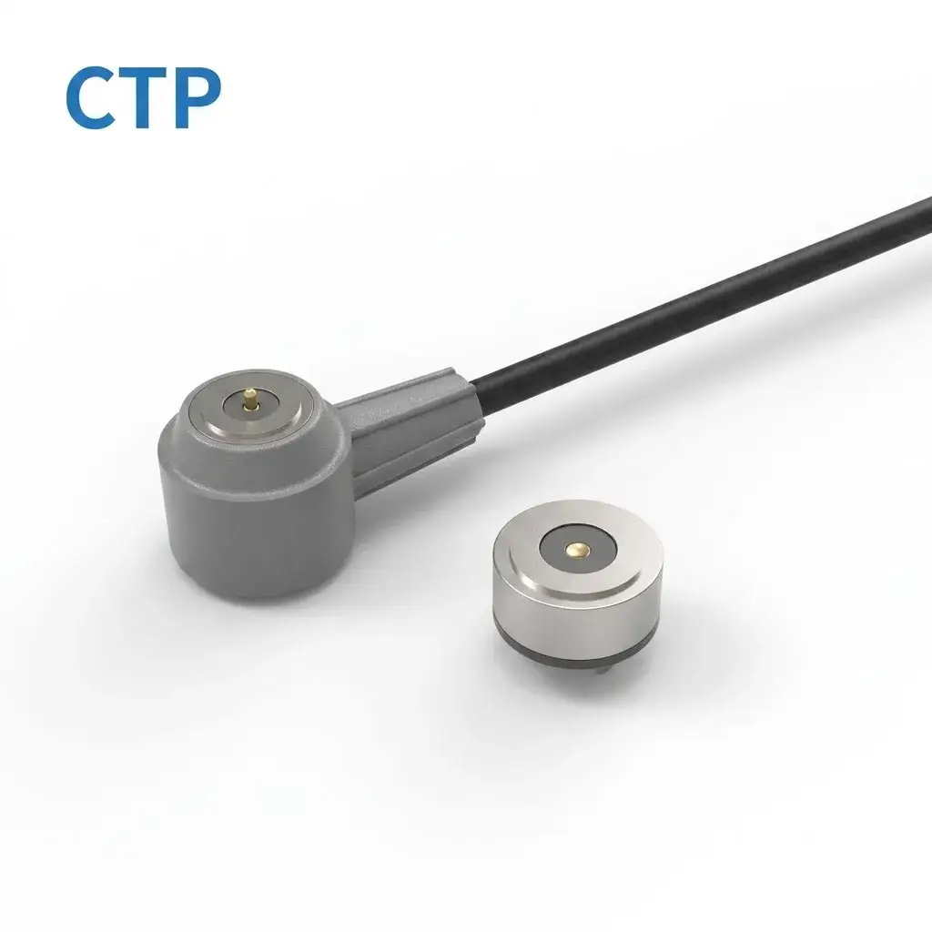
An axial magnetic lead gives a different kind of tidy connection
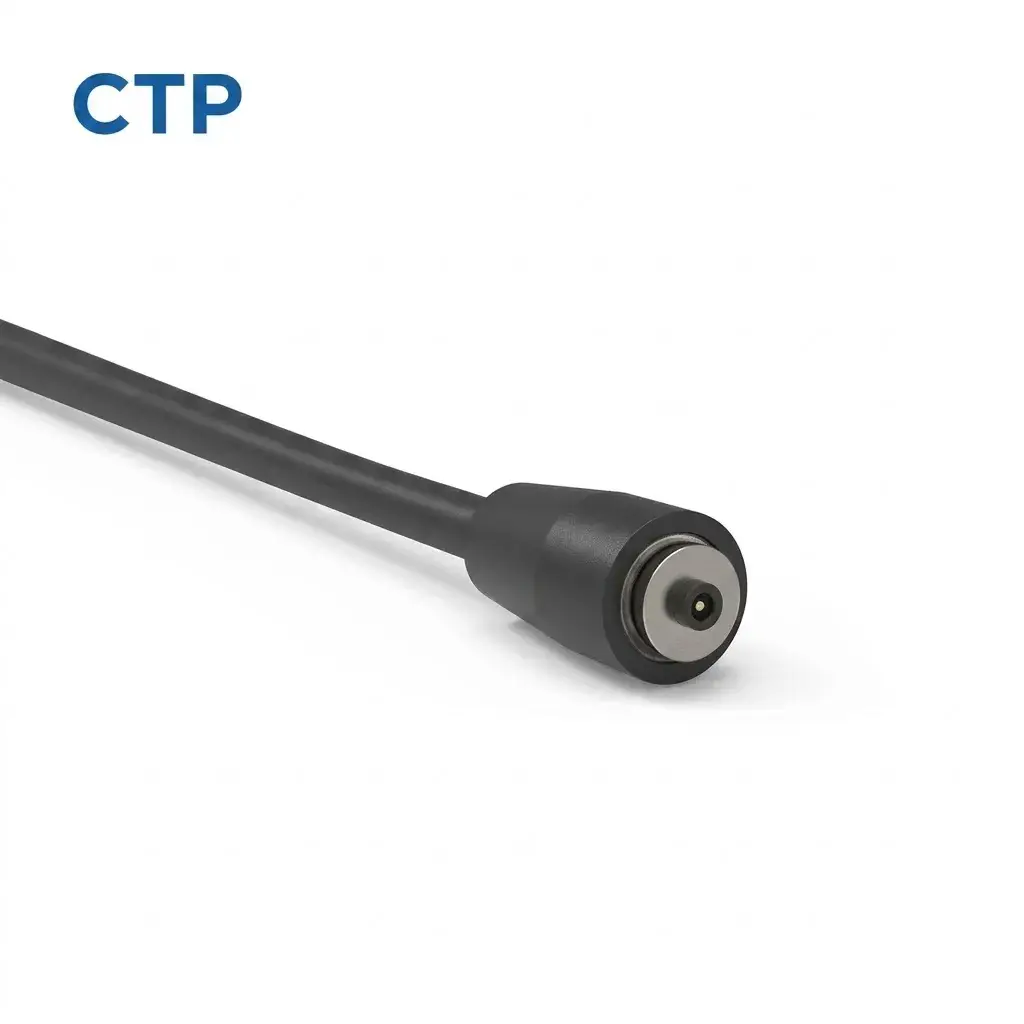
Some installations have useful space behind the connector rather than beside it. Our round magnetic connector with a rear axial lead, CTP-MC-1P-RD-A02, suits that type of layout. The cable leaves in line with the connector’s rear direction.
That direct route can look clean on an accessory whose lead naturally travels away from the mating face. The cable has room to form its bend farther behind the head, while the sides of the connection remain less occupied. It is a useful contrast to a side-exit design when you are comparing enclosure concepts.
A rear cable lead can keep nearby side controls accessible
Imagine a small device with a control wheel close to its round magnetic interface. A side outlet pointing toward that wheel could crowd the user’s hand. If there is enough depth behind the connection, an axial lead offers another route and can leave the control area clearer.
This product has one central electrical contact and a project-defined complete return arrangement. Its value in the layout discussion is the round mating structure with a rear lead. Cable length, construction, termination and strain relief can be reviewed for the route the product provides.
Magnetic cable exit orientation should follow the way the product is placed
A device may be used flat on a desk, upright on a stand or mounted against a panel. The same outlet direction can feel convenient in one position and awkward in another. Our custom development options let the connection be considered in the orientation the user will actually see.
For a desktop product, a route toward the back may leave the front face clear. For a panel-mounted product, a cable that follows the panel may occupy less useful space. For a handheld accessory, the best route may be the one that stays away from the area where the user grips the housing.
There is a simple visual advantage here: the lead can look as though it belongs to the device. It follows a deliberate path rather than appearing as something that had to be bent around the finished enclosure. That can help an OEM product feel more complete, even when the cable is a small part of the overall assembly.
The reference direction also has to be understood in relation to the device. A side outlet means little until its position relative to the display, mounting face or control area is clear. A product view showing the intended cable route makes the desired arrangement easy to discuss.
A USB-C cable offers a familiar source connection with room for a custom device end
The four-contact USB-C magnetic assembly, CTP-MCC-4P-USBC-DATA-01, combines a recognizable source-side plug with a magnetic cable head and matching PCB-mount connector. It is a useful route when the outside connection needs to work with a USB-C source while the device requires its own mating arrangement.
The PCB mate and cable outlet can share the same design conversation
The board connector has to fit the internal electronics, while the magnetic head has to meet the outside face of the product. Looking at both together allows the cable outlet to make sense for the complete connection. The source plug can remain familiar even when the device end is specific to the application.
On a small charging accessory, for example, the magnetic interface may sit near the lower edge of the enclosure. The free cable can be developed to leave toward the desk or behind the product, depending on how it will be placed. The four-contact electrical arrangement is defined for the intended functions.
This combination is useful because it gives the product team something concrete to work from: an integrated cable format and its corresponding mating part. Connector dimensions, retention, strain relief and cable construction can then be reviewed around that arrangement.
Two magnetic ends can give a modular product a consistent appearance
Our four-contact double-ended magnetic cable, CTP-MCC-4P-DME-DATA-01, connects two matched magnetic interfaces through one cable. It provides a different starting point when the lead joins two sections of a product rather than connecting a USB source to a device.
Think of a main unit and a removable accessory that are normally positioned beside one another. Each connection may need a different outlet direction to let the cable lie comfortably between them. Reviewing the two heads together allows their orientation to reflect that installed position.
The benefit is a more coherent interconnect. Both cable ends belong to the same product arrangement, while the lead between them can be sized for the intended distance. The device sections can look coordinated without forcing each end to occupy the same space or face the same direction.
The retention behavior can also be considered for each end individually. A modular product may want one interface to stay connected more firmly than the other. The appropriate behavior depends on the way those sections are handled, so it is developed with the overall connection rather than assumed from a single magnet description.
A useful outlet leaves room for the first cable bend
The molded head is only the beginning of the cable’s space requirement. The lead still needs room to turn into its installed route. An outlet already pointing in a useful direction can make that first bend easier to accommodate within the product’s surroundings.
For the display beside a panel, a side-exit round structure may allow the lead to follow the surface without an immediate turn behind the head. For the device with clear rear space, the axial version may give the cable a more direct approach. These are different benefits for different layouts.
Cable diameter and construction influence the available bend arrangement too. This is why our outlet, housing and strain-relief options are considered alongside the cable itself. The aim is a shape that works as a complete connection, from the magnetic face into the flexible lead.
It is also worth looking at how the product is moved during normal use. A cable that sits neatly while the device is stationary should still have a sensible route when the user reaches the connector or changes the device’s position. This turns outlet orientation into a handling feature as well as an appearance decision.
The same choice can help when a device is placed beside another piece of equipment. If the available gap is on the left, for example, the desired cable route should be shown relative to that gap and the device’s front face. This makes the reason for the outlet direction clear without relying on a label such as “left-hand cable” viewed from an unknown side.
For a custom version, connector dimensions and the outlet arrangement can be reviewed together. That lets the visible magnetic head, the free lead and the enclosure share one design intention. The result can be a neater connection area with a route the user understands simply by looking at the product.
Four magnetic cable structures with different layout benefits
The catalog gives you recognizable starting shapes to compare. That is useful when the project is still deciding where the connection should sit. Each structure suggests a different way to manage the lead around the housing.
| CTP structure | Its useful layout feature | A product situation it can suit |
|---|---|---|
| Round side-exit data cable | The lead starts beside the mating head | A device close to a surface or panel |
| Round connector with axial lead | A direct rear cable route | An installation with clear depth behind the connection |
| USB-C magnetic assembly and PCB mate | A familiar source plug with a defined device-side connection | A compact accessory with custom magnetic integration |
| Double-ended magnetic cable | Two magnetic ends developed for the same interconnect | Two detachable device sections joined by a short lead |
These descriptions are about physical arrangement. The electrical functions, mating geometry and final dimensions belong to the particular project. A round shape, for example, does not automatically promise unrestricted rotation, and an axial lead does not establish a current rating.
Keeping that distinction clear makes the product comparison more useful. You can choose a structure because it offers a practical layout benefit, then develop the details that make it work for your device.
A better cable route can make the product feel easier to use
The connection area is often small, but it is a place the user interacts with repeatedly. A well-chosen outlet can leave that area less crowded, make the lead easier to place and help the device sit comfortably in its usual position.
Our magnetic cable range offers several structures for exploring that choice. The cable-exit and strain-relief guide adds more detail when the project moves into the connector transition.
When choosing magnetic cable exit orientation, look at the product as the user will see it: on the desk, against its mounting surface or in the hand. The right starting structure lets the cable take a sensible route from the moment it leaves the head, which can make a small connection feel much more thoughtfully designed.