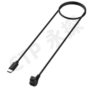
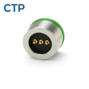
An industrial automation pogo pin connector is a spring-loaded electrical interface used where machines, tools, fixtures or mobile equipment must connect repeatedly without manual plug insertion. Typical applications include robotic tool changers, AGV charging docks, production test fixtures, removable sensor modules and automated pallet systems.
The primary engineering objective is not to promise zero downtime. It is to create an interface that mates repeatably, exposes early signs of degradation and can be cleaned, inspected or replaced without dismantling a large part of the machine.
In industrial automation, connector maintainability can be as important as initial electrical performance. A connector that works well but requires several hours to replace may still create unacceptable production losses.
Pogo pins should provide axial electrical contact. Machine guides, locating features, latches and structural frames should control alignment and carry mechanical loads.
Where Pogo Pin Connectors Fit in Industrial Automation
Industrial automation contains many detachable interfaces, but they do not all have the same mechanical or electrical requirements.
| Automation interface | Typical function | Primary design concern |
|---|---|---|
| Robotic tool changer | Connects grippers, cameras, weld tools or inspection heads. | Tool alignment, mechanical locking, contact sequencing and rapid replacement. |
| AGV or AMR docking station | Provides charging, identification or communication while docked. | Docking tolerance, contamination, charging enable and contact temperature. |
| Production test fixture | Temporarily contacts PCB pads or product terminals. | Cycle frequency, probe replacement, fixture calibration and false-failure control. |
| Automated pallet interface | Connects sensors, identification and power on a moving workpiece carrier. | Repeated indexing, pallet-position variation and contact accessibility. |
| Replaceable sensor module | Connects vision, measurement or condition-monitoring modules. | Module identification, signal allocation and maintenance replacement time. |
| Service and programming port | Supports diagnostics, firmware loading or temporary power. | Access control, correct orientation and low-frequency service cycles. |
A pogo pin connector is most useful when repeated docking, dimensional compensation or rapid module replacement creates a clear operational advantage.
Reliability in Automation Means More Than Long Contact Life
An industrial connector may complete many mating cycles and still cause production problems if it is difficult to inspect or replace.
For automation equipment, reliability normally includes four separate objectives:
- Functional reliability: the electrical interface performs within the required limits;
- Mechanical repeatability: every docking cycle produces suitable alignment and compression;
- Diagnostic visibility: developing faults can be detected before complete failure;
- Serviceability: damaged contacts or modules can be replaced within an acceptable maintenance window.
| Design objective | Engineering question |
|---|---|
| Electrical performance | Does resistance, voltage drop and signal behavior remain acceptable? |
| Mechanical repeatability | Does every tool or pallet reach the same working compression? |
| Fault detection | Can the control system recognize degraded contact before a line stop? |
| Maintenance recovery | How long does it take to identify and replace the failed interface? |
1. Separate Mechanical Docking from Electrical Contact
A robotic tool or AGV can introduce significant side load, impact and positional variation. These loads should not be transferred directly into the pogo pin plungers.
A robust docking interface may use:
- tapered locating pins;
- guide rails;
- hardened mechanical stops;
- floating connector plates;
- tool-side latches;
- robot-side locking mechanisms;
- pogo pins positioned behind the mechanical locating system.
Recommended docking sequence
- The robot or moving module enters the mechanical capture area.
- Guide features correct lateral and angular error.
- The structural faces reach their controlled stop position.
- The pogo pins compress within their approved working range.
- The locking system confirms secure engagement.
- The controller enables power and communication.
This sequence prevents the electrical contacts from acting as alignment posts.
2. Use Floating Contact Plates for Residual Misalignment
Even accurate robots and fixtures have repeatability limits. Thermal expansion, tool wear, frame movement and pallet variation can change the final connector position.
A floating connector mount can compensate for small residual errors after the main docking structure has completed most of the alignment.
A floating system may allow controlled movement in:
- the horizontal direction;
- the vertical direction;
- small angular directions;
- the compression axis.
The floating range should be limited. Excessive movement can create unstable connector position, uneven compression or cable fatigue.
Floating-mount design checks
- maximum permitted movement;
- return-to-center force;
- mechanical stop position;
- cable and wire flexibility;
- wear of guide bushings;
- effect on pogo pin compression;
- access for maintenance.
3. Divide the Contact Array by Function
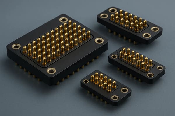
An industrial automation pogo pin connector may carry several circuit types through the same interface.
Typical contact groups include:
- main power;
- power return;
- control voltage;
- digital inputs and outputs;
- sensor signals;
- module identification;
- communication circuits;
- protective or functional ground.
These contacts should not be positioned only according to available space.
| Contact group | Layout priority |
|---|---|
| Main power | Short conductor path, suitable spacing and temperature-rise control. |
| Power return | Return capacity should match the outgoing current path. |
| Control signals | Separate from noisy power circuits where practical. |
| Identification | Engage before main power when the system must verify the tool or module. |
| Ground or shield | Placed according to the electrical return and EMC architecture. |
High-speed industrial Ethernet or other controlled interfaces may require protocol-specific connector design and validation. A general multi-pin pogo array should not automatically be assumed compatible.
4. Confirm the Tool Before Enabling Power
Automated equipment may connect different tools or modules to the same machine. Applying power before the controller verifies the connected device can create equipment damage or incorrect process operation.
A dedicated identification contact can allow the system to confirm:
- which tool is connected;
- whether the tool is fully seated;
- whether the expected ground path exists;
- whether the locking mechanism is engaged;
- whether the tool is permitted for the current program.
Example control sequence
- Mechanical docking is completed.
- A tool-present or identification contact becomes active.
- The controller reads the tool identity.
- The latch or lock sensor is confirmed.
- Power and communication are enabled.
- The machine begins the production cycle.
This architecture can reduce the chance of energizing an incomplete or incorrect connection.
5. Design for Replaceable Contact Modules
In many industrial systems, the connector is a wear component. The maintenance strategy should assume that the contacts may eventually require replacement.
A serviceable connector may use:
- a removable contact cartridge;
- replaceable pogo pin blocks;
- screwed rather than permanently bonded mounting;
- plug-in cable or PCB connections behind the contact module;
- accessible mounting hardware;
- alignment features that do not require adjustment after replacement.
Serviceability questions
- Can the connector be replaced without removing the robot tool?
- Can maintenance personnel access the mounting screws?
- Does replacement require soldering inside the machine?
- Must the connector be recalibrated after replacement?
- Can the mating counterpart be inspected at the same time?
- Is the replacement part keyed to prevent incorrect installation?
The connector should be treated as a replaceable service module when its expected wear rate is shorter than the service life of the complete machine.
6. Make Cleaning Possible Without Damaging the Interface
Industrial environments may contain:
- metallic machining particles;
- dust;
- oil mist;
- coolant residue;
- adhesive;
- welding contamination;
- packaging debris;
- cleaning chemicals.
Contamination can increase resistance, restrict plunger movement or prevent the connector from reaching full compression.
Contamination-control measures
- orient the contact face away from falling debris;
- add covers when the interface is not in use;
- use recessed contacts or insulating barriers;
- provide compressed-air or brush access where appropriate;
- avoid pockets where coolant can accumulate;
- define compatible cleaning materials;
- include visual inspection in maintenance procedures.
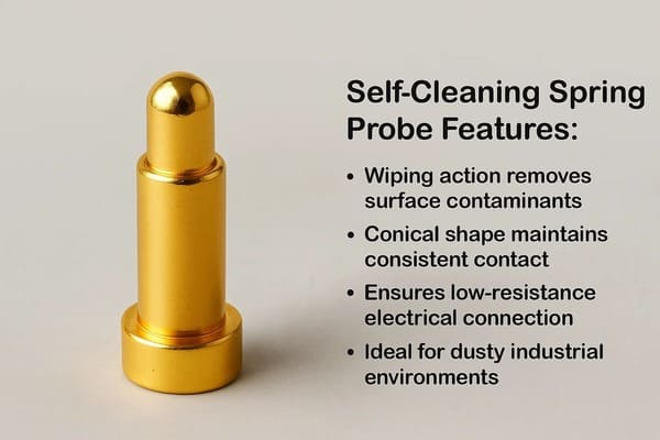
A wiping contact motion may remove light surface films, but it should not be described as a universal self-cleaning solution. Abrasive debris can make wiping wear worse.
7. Monitor Connector Health Before Complete Failure
Many pogo pin problems develop gradually. The connector may continue operating while resistance increases, one parallel contact stops contributing or mating becomes less consistent.
Industrial equipment can use several indicators to monitor connector condition.
Cycle count
The controller can record how many docking or tool-change cycles the interface has completed. Cycle count alone does not prove condition, but it provides a useful maintenance reference.
Voltage-drop trend
For power circuits, the machine can compare the voltage before and after the connector under a known load. A gradual increase may indicate contact degradation.
Temperature trend
Rising connector temperature under the same current and ambient conditions can indicate increasing resistance.
Connection retry count
Repeated tool-detection or communication retries may indicate intermittent contact before a complete open circuit occurs.
Docking-force or position change
Changes in robot position, latch travel or docking force can reveal mechanical wear that affects contact compression.
| Monitored parameter | Possible indication |
|---|---|
| Increasing voltage drop | Contact resistance, cable or termination degradation. |
| Increasing temperature | Unequal current sharing or local resistance increase. |
| Repeated identification failures | Low compression, contamination or module movement. |
| Longer docking time | Guide wear, robot-position drift or connector obstruction. |
| One parallel contact inactive | Remaining contacts may be carrying additional current. |
8. Set Maintenance Intervals from Evidence
A fixed mating-cycle number should not be copied from another product and used as the maintenance interval.
Maintenance frequency should consider:
- actual docking cycles per shift;
- electrical current and load duration;
- contact compression;
- factory contamination level;
- tool weight and vibration;
- cleaning frequency;
- measured resistance trend;
- history of connector-related alarms.
Example maintenance levels
| Maintenance level | Typical activity |
|---|---|
| Routine operator check | Visual inspection, debris removal and basic function check. |
| Planned maintenance | Measure installed height, spring movement, resistance and docking alignment. |
| Condition-based replacement | Replace the contact module after resistance, temperature or retry trends exceed limits. |
| Failure investigation | Review failed and good samples, machine logs, alignment and environmental conditions. |
9. Keep Test Fixtures from Creating False Production Failures
Pogo pins are widely used in production test fixtures, but the fixture contacts themselves can become a source of false failures.
Common fixture problems include:
- worn probe tips;
- contaminated contacts;
- fixture-plate deformation;
- uneven probe height;
- damaged wiring behind the probe block;
- incorrect fixture calibration;
- product misalignment inside the nest.
A false failure may cause unnecessary product rework or hide the true performance of the tested device.
Fixture-control measures
- use replaceable probe blocks;
- record probe-cycle counts;
- inspect reference or golden samples regularly;
- measure fixture resistance separately;
- verify product seating before testing;
- calibrate dimensional reference surfaces;
- separate fixture faults from product faults in the test software.
10. Review Cable and Harness Movement
Even when the pogo pin interface is stationary during operation, cables connected behind the connector may move with the robot, tool or drag chain.
Cable movement can introduce:
- pull force on the connector module;
- side loading;
- solder-joint fatigue;
- wire breakage near the termination;
- changes in floating-plate position;
- intermittent signals unrelated to the pogo pin itself.
Design controls
- add strain relief;
- route cables away from the connector’s floating movement;
- define minimum bend radius;
- support heavy harnesses independently;
- test the full drag-chain motion;
- monitor continuity while the robot moves through its working envelope.
11. Match the Connector to the Industrial Communication Protocol
Some automation connectors carry only discrete input and output signals. Others may carry serial communication, industrial Ethernet or sensor data.
The electrical requirements should be defined before selecting the contact layout.
Review:
- signal type;
- data rate;
- signal and return allocation;
- shield connection;
- connector-head PCB routing;
- cable type;
- permitted interruptions during docking or movement.
A pogo pin array that passes continuity testing does not automatically meet the electrical requirements of every industrial communication protocol.
Industrial Automation Validation Matrix
| Validation area | Recommended evaluation |
|---|---|
| Docking repeatability | Maximum positional variation across repeated tool changes or pallet cycles. |
| Working compression | Minimum and maximum pogo pin compression across the full array. |
| Live continuity | Electrical monitoring while the robot, tool or AGV is moving. |
| Tool identification | Correct and incorrect tool recognition before power enable. |
| Contamination | Dust, oil, coolant, metal particles and the approved cleaning method. |
| Cable movement | Drag-chain cycling, strain relief and continuity through the full motion range. |
| Contact aging | Resistance, spring movement and surface condition at defined cycle intervals. |
| Maintenance replacement | Replacement time, orientation control and function after service. |
| Fault response | System behavior after partial mating, one open contact or identification failure. |
When a Pogo Pin Connector May Not Be Suitable
A conventional industrial connector may provide a clearer solution when:
- the connection must remain positively locked under high continuous force;
- a standardized industrial fieldbus connector is required;
- the interface remains permanently connected;
- the environment contains uncontrolled conductive debris;
- the machine cannot provide accurate mechanical guidance;
- the connector cannot be inspected or cleaned safely;
- the circuit cannot tolerate exposed contacts;
- third-party cable compatibility is required.
In these cases, a mechanically latched circular connector, wire-to-board connector, industrial Ethernet connector or another standardized interface may be more appropriate.
Information Required for an Automation Connector Project
To evaluate a custom industrial automation pogo pin connector, provide:
- machine, robot, AGV or fixture type;
- exact connector location;
- number of docking cycles per shift;
- pin count and pin assignment;
- continuous and peak current;
- operating voltage;
- signal and communication requirements;
- available connector dimensions;
- robot or pallet positional repeatability;
- mechanical guide and locking structure;
- permitted lateral and angular misalignment;
- required working compression;
- factory contamination conditions;
- cable and drag-chain movement;
- required maintenance and replacement time;
- expected production volume;
- 2D drawings, 3D models and electrical diagrams.
Frequently Asked Questions
What is an industrial automation pogo pin connector?
It is a spring-loaded electrical connector used for repeated machine, tool, fixture or mobile-equipment docking. The pogo pins compensate for axial dimensional variation while the mechanical structure controls alignment.
Can pogo pin connectors eliminate production downtime?
No connector can supports zero downtime. A serviceable pogo pin interface can reduce certain connection and maintenance risks when it includes proper alignment, diagnostics, inspection access and replaceable contact modules.
Are pogo pins suitable for robotic tool changers?
Yes, especially for electrical power, control and identification circuits. The tool changer should use a separate mechanical lock and guide structure to carry tool loads.
Can an AGV use pogo pins for automatic charging?
Yes, provided the dock controls position, keeps the contacts de-energized until correct mating is confirmed and validates current, temperature and contamination behavior.
Do pogo pins clean themselves?
Some contact geometries create limited wiping action, but this does not remove all dust, oil or metal particles. Cleaning access and a maintenance procedure are still required.
How can connector degradation be detected?
Useful indicators include increasing voltage drop, higher contact temperature, repeated connection retries, longer docking time and changes in robot or latch position.
Should industrial pogo pins be replaced after a fixed number of cycles?
The replacement interval should be based on the tested connector, actual load, environment, maintenance history and measured condition rather than one universal cycle number.
Can pogo pin connectors carry industrial Ethernet?
Potentially, but the pin geometry, return paths, PCB transition, shielding and cable must meet the protocol requirements. Continuity alone is not sufficient validation.
Conclusion
An industrial automation pogo pin connector can support robotic tool changes, AGV docking, automated fixtures and removable machine modules. Its main advantage is not that it eliminates every possible signal drop, but that it can provide repeatable contact while supporting rapid maintenance and modular replacement.
The mechanical docking system should control position and carry structural load. The pogo pins should remain within their approved working compression, and the controller should verify tool identity and mating state before enabling the machine function.
For long-term uptime, engineers should also design cleaning access, replaceable contact modules and condition-monitoring methods. Voltage-drop trends, connector temperature, cycle counts and connection retries can help maintenance teams identify degradation before a complete failure stops production.
CTP supports custom development of individual pogo pins, pogo pin connector assemblies, magnetic pogo pin connectors and magnetic cable assemblies.
For a robotic tool changer, AGV dock or automation fixture, submit the pin map, current, signal requirements, docking tolerance, cycle frequency and maintenance target through our Get a Quote & Samples page. The contact module, mechanical docking structure and diagnostic strategy can then be reviewed together.