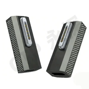
There is rarely spare space around the connector in a handheld product. The outer face needs to look right, the board needs room behind it and the removable head has to sit comfortably against the device. CTP’s magnetic connector range gives the mechanical team several ways to bring those requirements together.
Dimensioned power pairs, circular interfaces and FPC modules each offer a different installation route. A magnetic connector mating datum connects the selected part to the device’s final seated position. It is a useful design detail, but the product benefit is much more familiar: a mating face that sits where it should, with room for its contacts and termination to work.
CTP components give the enclosure design something concrete to work with
An attractive connector image can help start a discussion, but a product team needs more to place it in an enclosure. The shape of each half, its mounting relationship and its termination determine how the interface occupies the device. Our product references provide real formats to compare while those decisions are still open.
Separate plug and receptacle references on CTP-P4269
The CTP-P4269 two-contact DC pair has a published 2.54 mm contact pitch. Its dimensioned references show a 9 × 6.5 × 7 mm male part and a 12.1 × 11.6 mm female outline. Those are separate component references, useful for considering the accessory head and device-side opening together.
For a compact power product, this makes the initial packaging discussion more specific. The designer can look at how much of the head remains outside, where the mating part sits in the housing and how the internal connection leaves it. The selected mating drawing then establishes their combined seated relationship, rather than requiring the team to estimate it from an isolated front view.
The pair format is helpful here. There is a removable side and an installed side to develop, and both contribute to the product’s appearance and handling. CTP-P4269 gives that simple power interface a defined starting structure while the custom installation is worked out around the enclosure.
The mating datum keeps the magnetic face connected to the rest of the product
In plain terms, the datum is the reference used to locate or measure the interface. In a dock, it may be related to the surfaces where the device comes to rest. In an accessory, it may be tied to the mounting features that hold the contact carrier. The purpose is to connect the connector’s position to something the finished product actually controls.
This helps the design remain coherent as parts are added around it. The external head meets the device at one location, while the PCB, bracket or flex termination sits behind it. A shared location reference lets those parts be developed with the same seated relationship in mind. It is a practical link between the component drawing and the way the product is assembled.
Our magnetic connector formats accommodate different installation approaches. That is useful because the best mechanical reference is not the same in every device. A board-mounted connector, an FPC carrier and a panel-mounted circular part are held in different ways, even when all three provide magnetic attachment at the outside.
FPC modules give a thin product more freedom behind the face
The five-contact module separates the interface from the main board
The CTP-P3911 five-contact FPC module brings its contact paths out through a flexible printed circuit. The contact carrier can be positioned at the housing while the tail runs towards the electronics. This is valuable when a battery, a support or another component occupies the space directly behind the external connection.
For a shallow handheld, that creates an alternative to moving the entire PCB towards the opening. The connector face and main board can occupy the positions that suit their own jobs, with the flex joining them. The carrier still has a defined support, so the flexibility is used for routing rather than for leaving the mating face free to move.
The seven-contact format carries that freedom into a broader interface
The CTP-P3916 seven-contact FPC module offers the same type of termination with more positions to allocate. A device that needs several power and control paths can therefore consider a flex-connected magnetic face without forcing all the electronics immediately behind it. The installation benefit and the circuit allocation can be developed together.
Think of a product whose outer connection sits on a curved wall. The main board may be flat and set farther inside. An FPC route helps connect those locations, while the carrier mounting establishes the face position. The result is a more flexible layout discussion: the enclosure can serve the user’s grip, and the board can serve the internal assembly.
Round and right-angle formats offer other ways to place the interface
A circular face for a circular installation area
The CTP-MC-R10-3P-S01 round three-contact pair provides another outside form. Where the product has a round opening, this format gives the team a circular mating structure to evaluate. The contact pattern is located relative to the device, including an angular reference where the circuit requires one orientation.
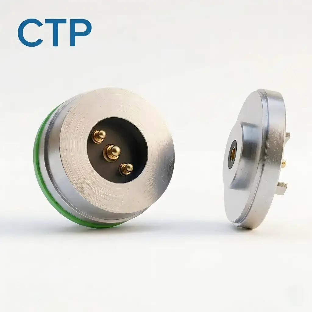
A circular installation can be useful on a rounded accessory or small panel. It gives the industrial designer a different boundary to work with from a rectangular contact face. Its value is in how it fits the complete product, including the mounting and rear termination, rather than in the outline alone.
For a board-led layout, the CTP right-angle magnetic connector reference offers a different termination direction. It is worth examining where a straight rear connection conflicts with the available board position. The selected drawing determines the footprint and support, giving the design another route between the visible interface and the internal PCB.
A supported spring contact makes the seated design useful
The spring-loaded contact is part of what makes these magnetic interfaces adaptable to a device assembly. At the intended working compression, it supplies contact pressure while allowing the selected amount of axial movement. The surrounding structure sets the final gap, so the contact and enclosure have complementary roles rather than competing for the same job.
For the OEM, this is a useful form of compliance. The connector does not depend on two rigid surfaces merely touching at an ideal nominal point. The approved contact movement is considered with the actual assembled dimensions. CTP’s working-stroke guidance explains that relationship in more detail.
It also helps clarify why a compact design needs to be viewed in section. A small change to carrier depth can alter the contact gap even if the outside opening stays the same. By considering the CTP component, its mounting and its mate together, the team can retain the intended contact position while developing the enclosure around it.
With an FPC module, the carrier support establishes the face while the tail handles routing. With a board-mounted structure, the PCB support participates in the installation. With the two-contact DC pair, the plug and receptacle each have their place in the housing. The range offers choices because these are genuinely different ways to build a product.
A better-fitting connector starts with the right installation route
For a shallow enclosure, compare the five- and seven-contact FPC modules early. For a focused power connection, consider the two-contact pair with both mating-half references in view. For a circular opening or a board that needs another termination direction, the round and right-angle formats provide useful alternatives. These choices let the product’s layout guide the connection.
The magnetic connector mating datum is then agreed for that route, along with the final gap and working contact position. Dimensions and tolerances belong to the selected configuration. The CTP mounting guide provides related context for the board and support decisions that complete the installation.
Bring a section of the enclosure and the intended board location to the development discussion. Those two views often explain the packaging problem better than a request for a smaller connector. CTP’s range can then be considered where it adds the most value: placing the magnetic face conveniently on the outside while giving its mounting and electrical connection enough room inside.