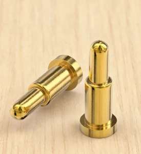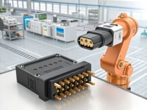
A small build gives you a chance to see the connection as part of the finished device. You can hold the accessory, place the instrument in its dock and see how the contact area fits the housing. Those ordinary actions tell you something that a photograph of a loose connector cannot.
Our PCB contact arrays, magnetic pairs and complete cable assemblies offer several ways to develop that experience. Connector pilot production approval is the stage where the selected arrangement is reviewed in the product and assembly it is intended to serve. The contact choice should support the way the device looks, connects and is put together.
A grouped PCB connector keeps several contact paths together
The CTP ten-contact non-magnetic assembly, CTP-PPC-10P-01, combines ten spring contacts with an insulating housing. It is an option for a product that already has guides, a carrier or fasteners to position and retain its removable part.
The non-magnetic block can work with the product’s own holding structure
Consider a removable electronics module that slides into a supported location inside an instrument. The product’s carrier can establish the seated position, while the pogo contacts meet the matching targets. The electrical connection fits into the existing module action without requiring magnetic retention.
The shared housing brings the contact positions together as one assembly. That gives the board and module designers a coordinated interface to arrange alongside their other components. The paths are assigned for the actual circuit, with each spring contact providing electrical pressure at its target.
For a pilot build, this means the complete connector can be considered in its real location. Its outline, target area and relationship to the carrier are visible together. The review can focus on the device the team intends to manufacture, rather than an isolated component.
Our ten-contact dual-row SMT array, CTP-PC-10P-DR-A01, offers another grouped format. It uses a five-by-two housing for surface-mount PCB integration. Where that mounting route suits the board, the compact array gives several assigned paths one defined contact pattern.
The two formats illustrate why the contact choice belongs with the board and enclosure. The number of paths may be similar, while the mounting and product integration differ. Comparing the complete parts makes those differences easier to judge during a small build.
A magnetic pair can make a removable accessory easier to attach
The CTP six-contact rectangular magnetic pair, CTP-MPC-6P-REC-PAIR-01, includes a spring-contact half and matching target half. Magnetic features assist capture and retention, while the pogo contacts provide electrical pressure.
A matching pair gives the accessory a deliberate connection point
For a removable control accessory, that can create a convenient attachment area on the device. The housing guides the two parts into the intended seated position, and the contact map carries the circuit functions assigned to the six paths.
In a pilot unit, the team can see how that connection feels alongside the rest of the product. The location should be easy to reach, the accessory should sit as intended and its removal should fit the way the product is used. The connector is one part of that experience, together with the enclosure and support features.

The advantage of a defined pair is that both sides are part of the same product discussion. Their contact pattern and housing relationship can be considered together before the device becomes a repeat production item. The electrical behavior still belongs to the approved circuit and complete assembly.
A complete cable can make the accessory route easier to develop
Our four-contact USB-C magnetic cable, CTP-MCC-4P-USBC-DATA-01, joins a familiar source plug to a magnetic head and matching PCB-side connector. It offers a complete format for a custom charging or supported power-and-signal accessory.
The USB-C-ended format brings the source and device connection together
For a small desktop instrument, the pilot can show the intended cable length, approach direction and resting position. The lead should reach comfortably while fitting the space around the product. The magnetic face and board-side mate can be developed with the enclosure opening and PCB location.
This is where a complete assembly format is helpful. The cable is more than an unspecified lead added to a connector. Its source end, conductors, molded parts and magnetic interface belong to the selected configuration, giving the product team a clearer accessory to evaluate.
The four contact paths are defined by the circuit and USB-C wiring. A source plug alone does not establish a charging protocol. Choosing the complete assembly makes it possible to discuss the required functions and physical route together.
The CTP six-contact magnetic harness assembly, CTP-MCC-6P-LIN-WH-01, provides a different route to internal electronics. Its linear head connects through six conductors to an opposite-end harness connector.
A dock with a board set back from the contact face may find that arrangement more natural. The magnetic head can stay at the device pocket while the cable reaches the internal board. In the pilot, the complete route can be considered with the enclosure, access and assembly sequence.
Connector pilot production approval can stay focused on the device
The contact formats also give different teams something concrete to discuss. The board designer sees the connector footprint and surrounding components. The enclosure designer sees the contact face, support and available opening. The person choosing the accessory sees the cable ends and the way the lead sits beside the device.
With the five-by-two SMT array, those conversations center on one compact board-mounted contact pattern. With the six-contact rectangular pair, they center on the corresponding spring and target halves. With the USB-C cable, the source plug and lead are part of the same product choice. Each format makes a different part of the connection easier to visualize.
This can help a small build resolve the physical details without losing sight of the product’s appeal. A handheld should remain comfortable to place in its dock. A detachable accessory should have a sensible approach direction. An internal module should meet its targets within the space already reserved for it.
The range is valuable because those products do not all need the same answer. You can compare an integrated PCB block, a magnetic pair and a harness assembly against their actual locations. The pilot then develops a chosen connection format around the equipment that will use it.
A useful pilot brings the selected parts into the arrangement intended for the product. For the PCB array, that includes the actual board and mating target position. For the magnetic pair, it includes both housings. For a cable, it includes the route and the opposite-end connection.
This gives the product team a chance to refine the details that affect everyday use. An accessory may be easier to handle with a different cable exit. A connector opening may be more convenient in a slightly different location. A grouped contact pattern may leave more useful room around the board.
For an instrument used on a desk, the benefit may be a tidier accessory arrangement. For an internal removable module, it may be a coordinated interface that works with the existing carrier. The appropriate contact format makes those product decisions easier to develop in the physical assembly.
For example, a team building a docked handheld can compare the magnetic face with the device’s seated position and the harness route behind it. The same build shows how easily the housing closes around that route. It gives the cable choice a real product context without turning every part of the review into a generic checklist.
A different team developing a retained electronics module can compare the ten-contact non-magnetic block with the module carrier. Its main interest may be how the target area and connector outline fit inside the enclosure. The spring interface serves the separable electrical connection while the carrier provides the holding action.
The sample approval guide provides more detail on evaluating a selected configuration. The pilot’s actual scope, evidence and release decision are set for the project, so the agreed result relates to the product and assembly being built.
Our range gives you several concrete starting formats for that work. An SMT array can organize a board contact area. A non-magnetic block can fit an existing carrier. A magnetic pair can support convenient attachment, and a cable assembly can join that interface to a source or internal board.
The most useful outcome is a connection that belongs to the device: accessible where the user needs it, suitable for the available board space and clearly defined for the intended assembly. A pilot build helps turn that selected format into a product arrangement the whole team can see and understand.