Putting a handheld device back in its dock should take one easy movement. The user lowers it into place, the magnetic interface helps bring the two sides together, and the device is ready for the next part of its working day. That is the experience behind a well-designed magnetic docking connection.
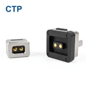
CTP offers magnetic connector components and FPC modules for products where the contact face is small, partly hidden or difficult to reach with a conventional plug. Blind-mate magnetic connector alignment brings the magnets, contact arrangement and surrounding device guides into one design. Our range gives an OEM several ways to build that connection, from a small round interface to a multi-contact dock.
A more convenient connection for devices that return to a cradle
A dock is used differently from a cable plugged in once and left alone. The device is picked up, used and returned. The connector has to work with the position of the user’s hand, the shape of the cradle and the direction from which the device arrives. Magnetic attachment is attractive here because it helps bring the mating parts together during that repeated interaction.
The spring contacts perform a different, complementary job. Once the parts are properly seated, their compliant movement provides contact pressure across the selected working position. The magnets assist capture and retention, while the product’s mounting and guiding features establish the final relationship. Together, these elements give the dock designer a useful alternative to making the user reach a small plug directly.
The CTP magnetic connector selection guide introduces several interface formats for this kind of development. The most useful choice is the one that supports the device’s actual movement and circuit requirements. A charging-only cradle and a dock carrying power, identification and controls do not need the same contact arrangement.
FPC modules keep the dock face independent of the main board
Seven contacts for a dock with several functions
In a cradle, the useful contact position is where the device naturally comes to rest. The CTP-P3916 seven-contact FPC module lets that position be considered separately from the main board: its supported face meets the device, and its flexible printed circuit takes the seven assigned paths back towards the electronics. The dock can be laid out around the docking movement.
This is useful when the dock’s best contact position does not line up with the main PCB. The face can be located where the handheld device naturally rests, while the flex takes the connection around the internal layout. It gives the enclosure and board designers another way to work together, rather than requiring the board to occupy the space directly behind the interface.

For an industrial handheld, that freedom can matter around the battery, enclosure supports and charging cradle. The connector can be developed at the point where the device meets the dock, with the internal route following the available space. The carrier is supported at the interface; the flexible tail connects it to the electronics without being asked to hold the face in position.
Five contacts when the docking circuit is more focused
The CTP-P3911 five-contact FPC module offers a similar termination approach with fewer electrical positions. It is a useful alternative when the dock needs a defined combination of charging and a smaller set of additional functions. Choosing between the modules starts with the circuit, then moves to the actual flex route and mounting arrangement.
Having both formats available keeps the discussion proportionate to the device. A simpler dock can use a focused interface, while a broader accessory can be evaluated with more contact positions. The FPC advantage remains the same: the product team has a route between the mating face and the board that can be considered with the enclosure layout.
Choose a mating face that works with the way the device arrives
The outside shape of the connection affects how it fits the cradle. A circular face, ring-type pair and dual-row interface offer different starting points for the guides, mounting and contact positions. CTP’s range lets those mechanical choices be considered alongside the number of circuits, which is helpful when the dock must feel natural as well as fit electrically.
A round three-contact head for a compact docking area
The CTP-MC-R10-3P-S01 three-contact round connector provides a circular format for a focused interface. It can be evaluated when a round opening suits the product and the circuit needs three paths. The housing and device guides then establish the intended orientation and final contact position.
For a small device that rests in a shaped cradle, the surrounding enclosure can do much of the broad positioning. The magnetic pair helps with the final approach, and the contact layout is developed for the seated condition. This division of roles allows the visible dock to stay simple while its internal features support a more controlled connection.
The CTP four-contact ring pair offers another mating geometry. It is worth considering where its contact and target arrangement suits the required functions and enclosure. Rather than forcing every dock to use one shape, the available formats let the project compare a circular or ring-type interface with the actual space and movement.
A configurable dual-row interface for a broader device brief
The CTP 2–8 pin dual-row series provides several contact-count options for custom projects. Its spring-contact and target halves, insulating insert, housing and perimeter sealing arrangement are considered as parts of the interface. That gives the team a range to discuss when the dock also has environmental or installation requirements.
For example, an outdoor handheld may need a removable charging connection in an enclosure with a defined sealing boundary. An indoor accessory may place more emphasis on a shallow face or additional signal paths. The series makes it possible to begin with the relevant contact count and mechanical structure, then develop the selected configuration around that device.
The advantage is having a connector discussion that covers more than the visible head. The mounting, contact compression and any sealing surface all contribute to the final seat. Considering them together helps the dock’s mechanical design support the electrical connection, rather than asking magnetic attraction to compensate for unrelated geometry.
What makes a magnetic docking interface feel well integrated
The user sees the top of the cradle and the part of the device that enters it. Behind those surfaces, several straightforward choices shape the experience. The entrance guides the device towards the connector, the stops establish its final position, and the cable or FPC leaves enough freedom for the face to remain correctly seated.
With an FPC module, a tidy internal route is especially useful. The tail can pass towards the board without occupying the contact-face location, but it still needs a supported path that does not twist the carrier. With a cable head, the first bend should work with the dock rather than pulling the head sideways. These details turn the choice of magnetic component into a more complete product solution.
The CTP PCB mounting guide covers related integration choices. For a dock designer, the practical benefit is being able to compare the termination and support early. The interface can then be placed for the user’s movement, with the electronics connected in a way the enclosure can accommodate.
A second useful application is a removable device module whose contact face is hidden once installed. Here, the approach features matter because the operator cannot directly see the tips meeting the targets. A suitable magnetic format can assist attachment, while the module’s guides and stops give the connection its final location. CTP’s different faces and terminations provide options for that combination.
Bring the CTP connector into the cradle design early
Choosing the connector while the cradle layout is still open gives the product team more useful choices. The five- and seven-contact FPC modules can be compared against the circuit. Round and ring-type faces can be evaluated against the opening. The dual-row series can be discussed where the project needs a particular mix of functions and a defined environmental boundary.
For blind-mate magnetic connector alignment, the final capability is established with the selected pair in the actual device. There is no single capture angle or offset that applies to every CTP structure. Working from a real configuration keeps the discussion specific while allowing the product’s intended ease of use to remain the main design goal.
A useful prototype includes the normal supports, the intended FPC or cable route and the surfaces the user handles. It shows how the connection behaves as part of the product, not just how two loose components attract on a desk. The custom connector guide describes the wider development inputs for moving towards that assembly.
For a dock used many times throughout the day, the connection deserves the same attention as the grip and cradle shape. CTP’s magnetic components give the project a choice of contact layouts and termination routes; your device brief gives those choices their purpose. Together, they can form a docking interface that is convenient to approach, neatly packaged and suited to the functions the equipment needs.