Two contacts may be all a charging accessory needs. Add device recognition, a control input or another signal, and the connector starts to serve a different purpose. CTP offers several contact counts so you can choose an interface for that purpose, with a shape and termination that also suit the product around it.
Choosing a magnetic connector pin count is therefore a product decision as much as an electrical one. A compact power pair keeps a simple device uncomplicated. A five- or seven-contact FPC module creates more options inside a thin enclosure. A fourteen-contact pair makes room for several functions at one removable connection. Here is how those choices differ in our range, and where each becomes useful.
A small power connection has a good reason to stay at two contacts
For a device that only needs a supply and return, a focused power interface can be an attractive choice. The external connection remains easy to understand, the wiring has a clear job and the connector does not need to accommodate unused signal positions. This is particularly useful when the product’s available space is limited and its charging function is already well defined.
CTP-P4269 gives a power-only product a compact starting point
The CTP-P4269 two-contact DC pair has a published 2.54 mm contact pitch. Its male dimension reference is 9 × 6.5 × 7 mm, while the female outline reference is 12.1 × 11.6 mm. These separate dimensions help the product designer evaluate both sides of the installation instead of looking only at the part visible outside the enclosure.
The two contacts can form a straightforward power connection in a suitable circuit. For a small accessory, that can be more useful than choosing a larger connector simply because it appears to offer more capability. The saved positions do not automatically translate into a finished-device size saving, but they allow the team to begin with a structure whose electrical role is deliberately simple.
There is still room for customisation around that simple role. The mating arrangement, installation and associated wiring can be reviewed for the device. A two-contact product should be selected because its two paths cover the requirement, with its complete electrical rating established for the chosen pair. It is a good fit when the simplicity serves the application, rather than a compromise made before the circuit is understood.
For an accessory used regularly, the two-contact format also keeps the electrical purpose easy to follow during development. There is one outgoing power path and one return to integrate. The team can concentrate on where the user attaches the head and where the device holds the mating part, rather than making room for signal paths that the product never uses.
What a third contact can add to a magnetic accessory
A third path can make an accessory more useful without moving immediately to a large contact array. It may be used for an identification input, a detection circuit or a control function, depending on the electronics. For a dock that needs to recognise something about the attached device, that extra route can be the difference between a simple power lead and an interface with additional functionality.
A round three-contact format suits a different enclosure shape
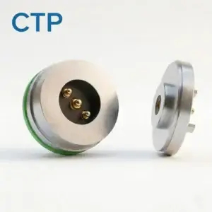
The CTP-MC-R10-3P-S01 combines three contact positions with a circular housing format. This gives the product team another choice when a round opening works better than an elongated face. The electrical allocation remains project-specific, so the third contact can be discussed in relation to the device rather than treated as a fixed factory function.
Imagine a charging stand for a handheld instrument. If the instrument only needs power, two contacts may be enough. If the stand also needs an identification response, the additional path deserves consideration. The controller still supplies the sensing and decision-making, but a three-contact structure can give that circuit somewhere to connect while keeping the external interface relatively focused.
The circular outline adds a packaging choice, not just an extra electrical position. It can be evaluated alongside the enclosure’s appearance, mounting arrangement and cable direction. If the circuits require one orientation, that requirement belongs in the design of the pair. With CTP, contact count and mechanical format can be discussed together instead of being selected as unrelated details.
This is worth considering when the product has a small connection area on a curved or rounded surface. A three-contact circle and a five-contact flex module may both satisfy an early feature list, yet lead to quite different enclosures. Starting from the actual CTP formats gives the industrial designer something useful to compare before the face shape becomes fixed.
Five or seven FPC contacts: more functions, more routing freedom
Our FPC modules are useful when the best position for the mating face is not directly above the main board. A flexible printed circuit carries the connection towards the electronics while the connector body is held at the device boundary. That gives a designer another way to organise a small enclosure, particularly when batteries, supports or other components occupy the space behind the face.
Five positions for a defined combination of power and signals
The CTP-P3911 five-contact FPC module provides five positions to allocate across the required circuits. A suitable design might combine a power pair with identification and control paths. The useful point is that these functions can be considered at one magnetic interface, with the flex tail connecting them to their destinations inside the product.
For a device with a settled feature set, five positions may offer a sensible balance. There is room for more than basic charging, without choosing the largest array available. The flex route can also help the team keep the connector in a convenient location for the user while placing the controller board where it works best for the rest of the assembly.
Seven positions when the dock has a broader job
The CTP-P3916 seven-contact FPC module provides two additional positions. It is worth evaluating when power, identification and several control or signal functions need to cross the same boundary. The extra contact count gives the circuit designer more allocation choices while retaining an FPC termination rather than requiring the main board to sit at the magnetic face.
Consider a product family with a basic accessory and a more capable version. A common seven-position interface may be useful if the planned circuits and mechanical design can share it. Alternatively, separate five- and seven-position products may make more sense. The advantage of a range is having both routes available for discussion, with the choice driven by the product plan rather than by a shortage of suitable formats.
The flex connection has a role in that choice too. If the device board sits to one side of the connector, the five- or seven-contact format can be considered with a route towards that board. This may be more valuable than saving a position at the magnetic face and then struggling to connect it internally. The useful comparison is between workable installations, not contact counts printed on their own.
Fourteen contacts bring several device functions into one mating area
A multi-function removable module may need a broader interface than a small charging accessory. Several signals, supplies and references can be easier to organise when they are considered together, rather than added through separate external connectors as the design develops. This is where a larger contact arrangement becomes a purposeful product choice.
The CTP-MPC-14P-DR-A01 fourteen-contact pair uses two rows of seven contacts. Its 7 × 2 layout offers a different installation option from the smaller round or FPC structures. The matching spring-contact and target halves provide a defined pair for a project that needs several electrical paths at one connection.
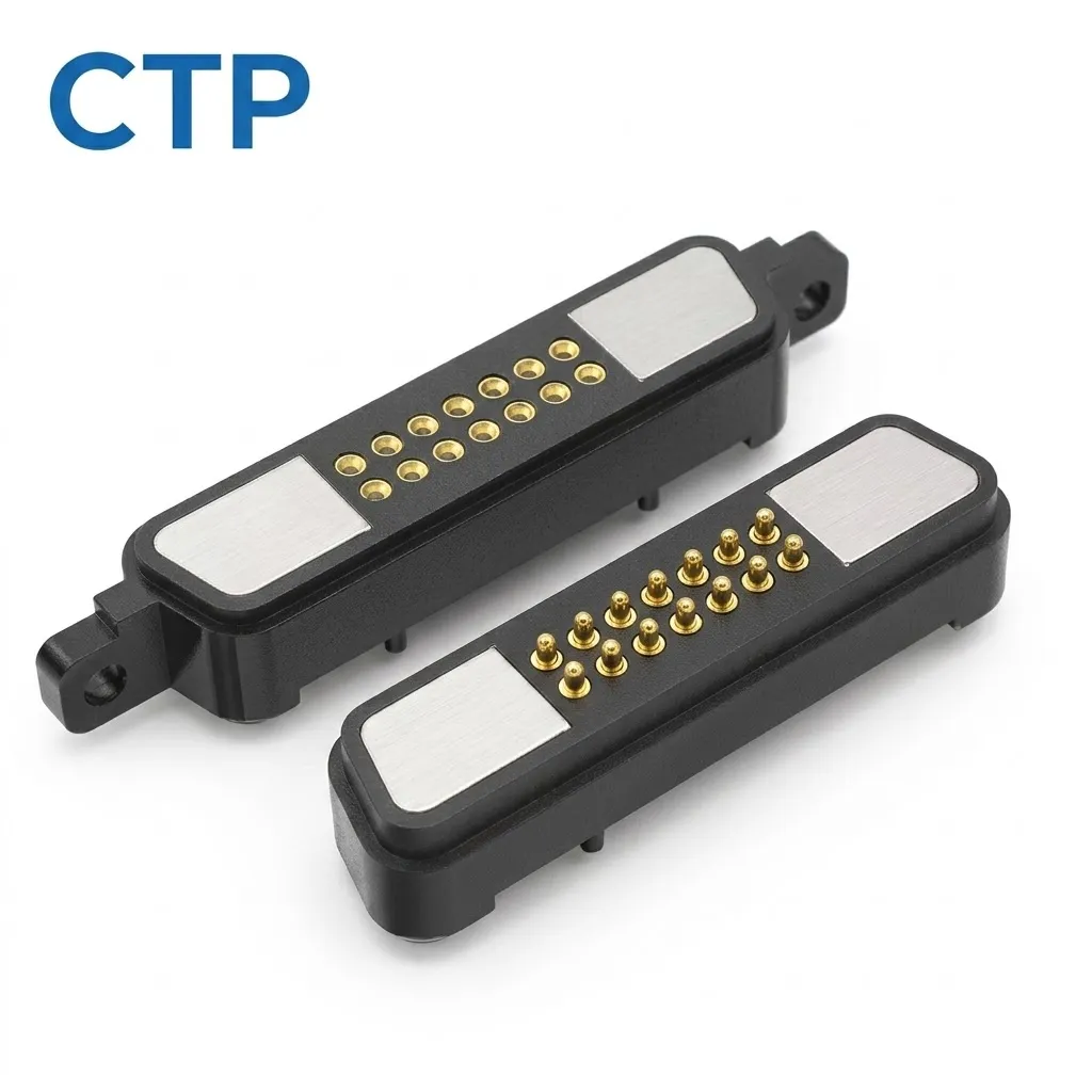
For an equipment module, that may allow the power, control and accessory functions to be grouped into one connection area. The benefit is not the number fourteen by itself. It is the opportunity to organise the required paths in a layout that can be evaluated with the enclosure and electronics as a whole. Each position should contribute to that purpose, including any spare reserved for an actual planned function.
The two-row shape can also be a better starting point for an elongated mounting area than a circular connector with a similar number of functions. It lets the team discuss the contact arrangement and housing proportions together. That is a concrete advantage of having several formats in the CTP range: the electrical requirement does not have to dictate one outside shape before the product layout has been considered.
Comparing the CTP contact counts at a glance
The following comparison is a starting point for discussing the range. The examples describe possible roles; the final allocation and electrical performance belong to the selected assembly. Contact count helps narrow the choice, while the mounting and termination decide how comfortably that choice fits the finished product.
| CTP format | Useful starting role | What the format adds |
|---|---|---|
| CTP-P4269, two contacts | A focused supply-and-return connection | A compact DC mating pair with dimensioned component references |
| CTP-MC-R10-3P-S01, three contacts | Power with an additional project-defined path | A circular interface option |
| CTP-P3911, five contacts | A defined mix of power and control functions | Flexible-circuit termination |
| CTP-P3916, seven contacts | A dock or accessory with more circuit functions | More allocation choices with an FPC route |
| CTP-MPC-14P-DR-A01, fourteen contacts | A multi-function removable interface | Two rows of seven positions in a matching pair |
Choose the count for the product you intend to build
The next step is to turn a feature list into actual connections. One function may need more than one conductor, while another may use a reference already present. A separate seating detector can require a path of its own. This is a short but useful discussion to have before the mechanical team commits to a particular face size.
For example, a circuit using supply, return, identification and a control line occupies four positions under that allocation. A separate detection path would bring it to five. If the electronics require another reference, the requirement changes again. Working through those connections makes the difference between CTP-P3911 and CTP-P3916 concrete, rather than treating the seven-contact option as an automatic upgrade.
Once the paths are clear, compare the installation. A circular head may suit the panel better, while an FPC termination may free the board from the contact-face location. A two-row arrangement may be worth considering for a broader module. The CTP custom connector guide brings these choices together with the rest of the device requirements.
For a buying team, this makes a product comparison easier to use. Instead of a list of increasing pin counts, the options become a power pair, a round accessory interface, a flex-connected module or a broader two-row connection. Each describes a way to build the device. The selected contact count then follows a design direction that the electrical and mechanical teams both understand.
Samples then have a clear job: show how the chosen interface fits and functions in your assembly. The sample approval guide is helpful when moving from the selected format to the actual mating parts. Ratings, working compression and any environmental requirements can be agreed for that configuration, without assuming that contact count alone establishes them.
Start with the simplest CTP format that comfortably serves the product, then move up when there is a real circuit or development reason. You retain the convenience of a magnetic connection and gain a choice of electrical and mechanical formats, with the space devoted to functions your device will actually use.