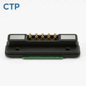
CTP magnetic connectors can bring charging, control and accessory connections together in an interface designed for your device. The magnetic connector pin map is where that custom fit begins. You decide which circuits need to cross the connection; we offer connector and cable structures that can accommodate those functions, from a compact two-contact power pair to a multi-contact FPC module or finished magnetic lead.
That gives an OEM more freedom than choosing a connector by its appearance and adapting the electronics around it. You can develop the contact arrangement, mounting position and termination as parts of the same product. The result is a connection with a clear purpose: the right electrical paths in a form that suits the enclosure and feels convenient to use.
Your circuits, in a CTP magnetic connector
Our magnetic connector range includes different contact counts, shapes and termination styles because a charging accessory and a multi-function dock have different jobs. A power-only connection can stay simple. A device that also exchanges identification or control signals needs room for those functions. Custom pin assignment lets the interface follow that distinction instead of leaving useful circuits outside the connection.
For a handheld instrument, that may mean bringing charging and a control input through one detachable head. For a docking station, it may mean keeping the power pair, an accessory-identification path and other signals in a single contact arrangement. These are possible project configurations rather than fixed pinouts. The useful starting point is the circuit your product needs, with the physical connector chosen around it.
A well-matched interface also makes the finished product easier to explain. The user sees one place to connect the accessory, while the electronics behind it can carry several functions. Inside the device, the contact map gives the PCB and cable teams a common arrangement to work with. That combination of a simple external connection and a tailored internal design is a central reason to consider a custom magnetic system.
CTP-P4269 keeps a two-wire power connection compact
The CTP-P4269 two-contact DC pair is a straightforward place to start when the interface only needs supply and return. Its published contact pitch is 2.54 mm. The dimensioned references show a 9 × 6.5 × 7 mm male part and a separate 12.1 × 11.6 mm female outline, giving the enclosure designer actual component dimensions to evaluate early.
The attraction of this format is its simplicity. Two electrical paths can keep the connector allocation and associated wiring uncomplicated for a suitable power-only product. There is no reason to add a larger contact array when the device has no use for it. Conversely, if accessory recognition is part of the brief, we can discuss a structure with more positions rather than squeezing an additional function into an unsuitable two-wire arrangement.
There is also a difference between buying a contact and buying a mating pair. CTP-P4269 gives the project a plug-and-receptacle structure to work with, so the discussion can cover the device side and removable side together. The product team can consider the visible opening, the internal mounting and the accessory head as connected parts of the same design.
An FPC termination puts the contact face where you need it
Small devices often have an awkward relationship between the best place for the external connector and the available space on the main board. Our FPC magnetic modules give those two locations some independence. The magnetic contact face can sit at the device boundary while the flexible circuit routes the connection towards the electronics, making the connector part of the enclosure design rather than an obstacle to it.
Five contacts for a focused power-and-control interface
The CTP-P3911 five-contact FPC module provides five positions with a flexible printed circuit termination. Depending on the circuit, those positions can accommodate a power pair and additional identification, control or signal functions. The benefit is having more electrical options at one magnetic face while retaining a flex route inside the product.
Picture a compact accessory with its connector on the front and its controller board set farther back. A flex connection can follow that separation without requiring the main PCB to sit immediately behind the mating face. The contact allocation still belongs to your circuit, but the product format gives the mechanical team a useful way to connect the two locations.
Seven positions give a more capable dock room to grow
For a broader set of functions, the CTP-P3916 seven-contact FPC module offers two more contact positions. That can be valuable when a dock needs to do more than charge. Identification, detection and control paths can be considered alongside the power connection, with the FPC carrying the chosen arrangement back into the device.

There is a practical development advantage here. If the product team expects two accessory versions, the electrical allocation can be considered alongside both versions before the enclosure is fixed. A spare position may be useful for a planned function, while a five-contact arrangement may remain the better fit for a simpler device. The range gives you options without assuming that more contacts are always better.
The same pin map can continue into a finished magnetic cable
CTP supplies magnetic connector components and finished cable assemblies. That matters when your project needs a complete lead rather than a loose connector for in-house integration. The magnetic head, conductors, cable length, overmould and opposite-end termination can be considered together, so the cable is developed for the device instead of being treated as an unrelated accessory.
Our four-contact magnetic cable with a USB-C opposite end is one example. Its magnetic interface provides four electrical paths, and its cable specification is project-specific. A suitable circuit might use those paths for power and signals, or for a charging connection with identification and detection. The actual functions are agreed for the complete assembly.
For the buyer, this makes the supply scope clearer. You can discuss the lead as something that must connect a particular source or host to a particular device, with the correct mating part at the device side. Cable length and conductor choice then have a real application behind them: where the device sits, how the lead is routed and what the electrical path must carry.
The USB-C plug shape is only one part of that description. Data capability, power behaviour and wiring follow the selected design, rather than being promised by the shell alone. We keep that distinction straightforward because it helps define the cable you actually need. It also leaves room for a custom opposite-end connection when USB-C is not the right choice for the project.
More circuits without scattering connections around the enclosure
When several functions cross a removable boundary, separate connectors can consume panel space and complicate the accessory. A multi-contact magnetic pair offers another route: bring the required paths into one mating area, with each position assigned to a particular role. The value is especially clear when the product needs one convenient external connection but has a more involved circuit behind it.
The fourteen-contact pair provides a two-row layout
The CTP-MPC-14P-DR-A01 uses fourteen contacts in a 7 × 2 arrangement. Its elongated, dual-row format gives a different packaging option from an FPC module or circular head. It can be considered for a removable module with several power, signal or control paths, subject to the electrical and mechanical requirements of that assembly.
The extra positions are useful when they have a job. A designer can discuss the allocation of supplies, returns, controls and reserved functions on the same face, rather than discovering late that a required path has nowhere to go. This also gives purchasing a more complete product description than “a fourteen-pin connector”: the selected pair has a defined role in the device.
Grouping the functions at one face can be particularly appealing for a removable control accessory. The person using it has one mating action to perform, even though several circuits cross the boundary. Behind the face, the two rows give the electronics team a physical arrangement to work from. The connection can look straightforward on the outside without forcing the device to give up useful control or signal functions inside.
Clear mating views make the custom design easier to build
A custom interface should be easy for the people assembling it to understand. We identify contact functions against the appropriate mating view, then carry those identities through any FPC or cable termination. It is a small part of the design discussion, but it connects the visible product to the circuit behind it and helps everyone work from the same arrangement.
For example, the front of an FPC connector and the exposed copper side of a folded tail may appear to run in opposite directions. Showing both views makes the relationship clear. On the fourteen-contact pair, row identification does the same job. On a finished cable, the map continues to the opposite-end terminals. Each format gets the information needed to describe its own construction.
That approach is useful when a product moves from an early sample to a repeat order. The connector reference identifies the structure, while the agreed map identifies its electrical configuration. If the device changes, the affected connections can be reviewed directly. The existing custom magnetic connector guide explains how these electrical and mechanical choices come together during development.
Choose the CTP format that makes your device easier to connect
The strongest reason to customise a magnetic connector pin map is that your product has a particular job to do. A small charging accessory benefits from a focused two-contact solution. A thin enclosure may benefit from an FPC tail. A multi-function dock may need more circuits at one face, while a finished cable project benefits from considering both ends of the lead together.
These options also change what your team has to integrate. A connector component suits a design where the PCB and harness work remain with your own assembly. A finished magnetic lead suits a project where the external cable needs to arrive as a coordinated assembly. Being able to discuss either route with CTP helps keep the supply choice aligned with the work your team wants to retain.
The same flexibility is useful when the cable is part of the product’s presentation. Its length can suit the distance to the dock, its opposite end can suit the intended host and its magnetic head can match the device-side interface. Those decisions belong together. A custom contact map is the link between them, keeping the visible accessory and its less visible wiring focused on the same task.
For an initial project discussion, the most useful information is the function of each connection, the available space and the preferred termination. From there, the conversation can move to a real CTP structure and its mating part. Dimensions and electrical performance are agreed for that configuration, with samples reviewed as part of the finished device rather than chosen only from a photograph.
If your next product needs charging and a few extra functions in one detachable interface, start with the five- and seven-contact FPC options. If it only needs a power pair, look at CTP-P4269. With the contact functions and available space in hand, we can discuss a specific mating pair or finished cable instead of leaving your team to adapt the device around a generic lead.