A magnetic lead should feel easy to attach. Bring the head towards the device and the magnets help the two halves come together, while the contact arrangement carries the circuits the product needs. For a charging accessory used every day, that small interaction is a visible part of the product’s quality.
At CTP, magnetic connector polarity is considered alongside the shape of the mating pair and its electrical assignment. This lets us discuss how the head approaches, which orientation the device uses and where the power and signal contacts belong. The aim is a convenient connection built around the product, whether that calls for a simple DC pair, a circular interface or a finished magnetic cable.
Magnetic attachment makes the connection part of the product experience
A small device may be well designed in every other respect yet awkward to connect. The user has to find the socket, hold a tiny plug in the right direction and push it into place. A magnetic mating format offers a different interaction: attraction helps bring the head towards its mate, and the surrounding design establishes its final position.
That can be appealing for a wearable accessory, a desktop charging lead or a removable device module. The connection becomes something the user can approach naturally, rather than a deeply recessed socket they need to reach precisely. The actual ease of attachment depends on the chosen pair and enclosure, but the magnetic format gives the product team useful freedom to shape that experience.
Our magnetic connector range includes several ways to do this. Small power pairs keep a focused electrical role. Round and ring arrangements offer different face shapes. Multi-contact products make room for functions beyond charging. The right choice brings the electrical requirement and the user’s attachment action into the same design discussion.
A two-contact DC pair can keep daily charging straightforward
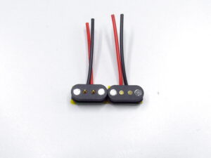
The CTP-P4269 is a two-contact magnetic DC pair with a published 2.54 mm contact pitch. Its compact plug-and-receptacle format can be considered where the removable connection has a supply-and-return role. The separate male and female dimension references help show how each side can be integrated into the accessory and device.
For a power-only lead, there is an advantage in giving each contact a clear job. The device-side part, removable head and wiring can be developed as a pair, with the intended orientation reflected in the electrical map. The user sees a simple attachment point; the product team has a defined connection behind it, rather than a head chosen only because it looks similar to another cable.
The two-contact option also suits a focused conversation about the product’s use. Where should the cable leave the device? How much of the head should remain available to grip? Is the accessory normally removed by pulling straight away or lifting one side? These questions help shape a convenient charging connection without adding circuit positions the application does not need.
How magnetic connector polarity supports the intended orientation
The magnet arrangement helps establish how the mating halves attract. The housing and locating features determine how they sit together. The electrical map defines which contact carries supply, return or another function. CTP’s custom development approach allows those choices to be discussed together, so the desired attachment action can be translated into a practical connector configuration.
There is no universal rule connecting a north-facing magnet with a positive power contact. The magnet poles and the electrical circuits have different roles. Keeping their relationship clear is useful because it leaves the design free to serve the product: the chosen magnet orientation can support the intended approach while the contact assignment follows the device’s actual circuit.
For general terminology, Harwin’s explanation of polarization and keying distinguishes controlling a pair’s orientation from distinguishing otherwise similar pairs. In a CTP project, that distinction helps clarify whether the requirement is one permitted attachment direction, separation between accessory types, or both. It is a focused design choice, rather than a vague request for a “polarity-proof” head.
A round interface gives the enclosure another design direction
Three contacts in a circular format
The CTP-MC-R10-3P-S01 round three-contact connector is an option when a circular connection area suits the device. Compared with a two-contact power pair, it gives the circuit an additional path to consider for a defined identification, detection or control role. The circular shape also offers a different visual and mounting arrangement for the enclosure.
For a portable device, a round face can sit naturally within a rounded product form. The team can consider the contact pattern, mounting position and cable direction together instead of reshaping the enclosure around an unrelated plug. The permitted orientations still follow the selected pair’s drawing, but the outside form gives the industrial designer a useful choice.
Five-contact and ring formats for a different circuit layout
The CTP-MPC-5P-RD-HT-A01 five-contact round pair provides another way to bring several paths to a circular mating area. It is worth evaluating where the accessory needs more than a simple power connection but the product still benefits from a round face. Its spring-contact and target halves are considered together with the intended wiring.
Our four-contact ring pair offers a different contact-and-target geometry. The value of having these alternatives is that the connection does not have to follow one outside pattern for every application. The electrical functions, target arrangement and surrounding enclosure can guide the selection of the pair.
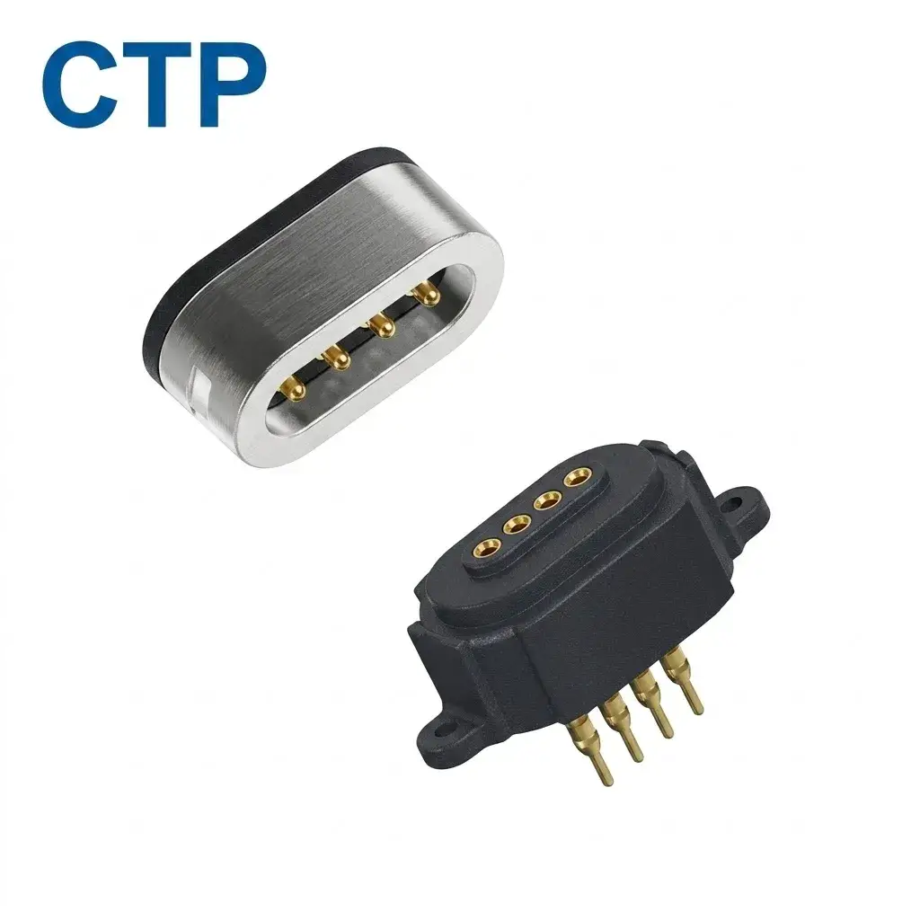
A round or ring appearance should be matched to the movement the product actually requires. Several allowed attachment positions and continuous powered rotation are different uses. We keep that distinction in the design brief, then focus on the configuration that serves the intended action. For a charging accessory, convenient attachment in the required positions may be all the freedom the user needs.
A coordinated cable makes the magnetic head more useful
The magnetic head is the part the user notices first, but its cable has a large influence on how the connection feels. Cable direction, the first bend and the overmould determine where a pull reaches the head. A neatly positioned connector can be inconvenient if the lead immediately turns into a strap, a stand or the edge of the enclosure.
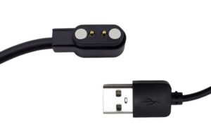
CTP’s four-contact magnetic cable with a USB-C opposite end shows how the head can be supplied as part of a complete lead. The cable conductors, length and opposite-end termination are considered with the magnetic interface. That gives the project a way to coordinate the visible accessory with the device-side mating part.
For a wearable charging lead, the practical benefit may be a cable route that keeps the head accessible while leaving the strap clear. For a desktop product, it may be a lead that reaches the intended source without being stretched tight across the device. These are application requirements to develop, not standard dimensions imposed on every cable using the same magnetic face.
The complete pin map also follows the lead to its opposite end. That is useful when the accessory carries a control or identification function as well as power. The USB-C shell does not define every circuit inside a custom cable; the agreed assembly does. A finished-lead approach brings those details into the same supply scope as the magnetic head.
A product family benefits from intentional accessory matching
If your device has more than one detachable accessory, the connection needs to communicate which one belongs where. A charging lead and a sensor accessory may have different electrical jobs even if both use magnetic attachment. Their shapes, magnet arrangements and circuit assignments can be considered together so the family has a deliberate connection design.
This is where customisation becomes more than choosing a colour or cable length. The interface can be discussed in relation to the functions of each accessory and the way the user approaches the device. A distinct housing or orientation arrangement may be useful where one shared-looking head would create confusion. The appropriate solution depends on the product family and its electronics.
For development teams, CTP’s range gives the discussion real starting points: a focused DC pair, a three-contact circle, a five-contact round pair or a ring-type face. Each offers a structure to compare with the required accessory role. You can work towards a coordinated product family while retaining different electrical definitions where the functions require them.
The anti-mismating design guide covers the related interface considerations. The important commercial benefit is a more intentional product: the accessory does not merely attach somewhere on the enclosure; its mating action and electrical role have been developed for that location.
Give the user a connection that belongs to the device
A convenient magnetic connection combines several small decisions. The head has a form the user can find and handle. The magnets assist its approach. The housing establishes the intended seat, and the contact assignment connects the functions the device uses. CTP’s component and cable options allow those decisions to be brought into one project rather than solved separately.
Electrical protection remains a matter for the complete device circuit, and attachment, removal and wrong-accessory behaviour are evaluated for the selected assembly. That keeps the product description accurate while leaving the design focused on the benefits: a tidy external interface, a suitable contact arrangement and a cable that works with the way the device is held or docked.
A simple power accessory may benefit from CTP-P4269; a circular product may lead towards the three- or five-contact options; a finished lead may suit the four-contact cable route. For a wearable charging lead, the next decisions can be quite tangible: a cable exit that clears the strap and a head that is comfortable to grip. The electrical design and magnetic pair then support that everyday use.