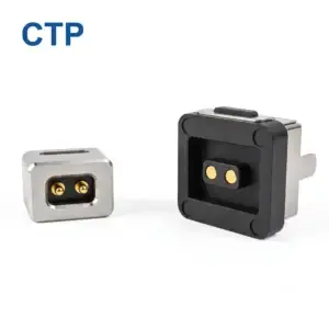
Pressing the module makes the connection return. Letting go makes it disappear again. It is tempting to blame the spring pin immediately, but the symptom can also come from the installed distance, a target that does not land where expected or a board that moves when the housing closes.
Pogo pin intermittent contact troubleshooting should follow the contact through its real seated position. Look at the plunger, mating target, support and electrical path together. CTP’s individual contacts and housed arrays give the designer different ways to build that relationship, including protected-body pins, compact dual rows and longer single-row assemblies.
Does the pogo pin reach its target when the module is seated?
The contact’s free position is not its operating position. A spring-loaded pin needs the intended compression against its target once the device has reached its stop. If a cover, carrier or board support holds the target too far away, the interface may connect only when an extra hand pressure changes the gap.
Check the relationship shown in the selected part drawing rather than pressing the plunger farther until the symptom disappears. Excessive compression can create a different problem. The purpose of the inspection is to reproduce the approved installed condition, not find any position in which a meter shows continuity.
An individual housed contact still depends on its surrounding installation
Our spring-loaded contact with an outer body, CTP-PP-1P-WP-A01, is a product option for project-specific mechanical integration. Its contact tip and outer structure need to be considered with the actual target and mounting arrangement.
A protective or sealing-oriented body does not establish the device’s final contact pressure by itself. For a removable enclosure panel, show how the panel stops and where its conductive target sits at that stop. That view is more useful than judging the contact from the exposed length visible before assembly.
Does a compact contact array sit squarely against the mating surface?
A six-contact dual row keeps a small contact group coordinated
The CTP six-contact dual-row PCB connector, CTP-PC-6P-DR-A01, brings six spring contacts together in one housing. It can suit a compact module whose functions need a coordinated group of contact positions.
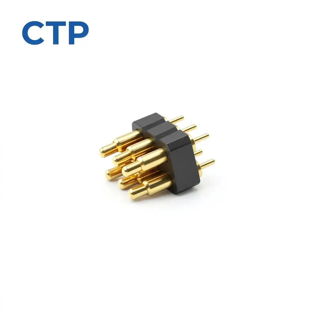
If only one part of the group connects, look at the seating of the complete assembly. A tilted target or unsupported board can leave different contacts at different installed distances. The integrated housing defines the pattern; it does not make the opposite surface flat or stop the device from rocking.
For a handheld accessory that is secured by a cover, compare the contact relationship before and after the cover is fastened. If fastening changes the symptom, the support and housing deserve attention before the team changes to another pin.
Does a long pogo contact row have support at both ends?
Thirty positions make the full mating span important
Our thirty-contact single-row assembly, CTP-PC-30P-SR-A01, provides a long coordinated contact arrangement. It is a very different physical format from a small dual-row block, and its mating surface needs to be considered across the entire span.
A module can appear properly seated near its latch while lifting slightly at the other end. With a long row, inspect the support and target relationship along the row rather than at only the most accessible contact. Each assigned path still needs the intended installed condition.
A wider removable control board might benefit from that linear contact format if its layout calls for many neighbouring paths. A compact module may be better served by a shorter dual-row arrangement. CTP offers both proportions, letting the contact layout follow the product rather than forcing the housing around one standard outline.
Is the fault at the plunger, the target or the board termination?
The CTP eight-contact through-hole connector, CTP-PC-8P-DR-A0X, uses a four-by-two contact arrangement with straight PCB tails. It offers another compact board-mounted route for a project with a defined multi-contact target.
When investigating intermittent operation, keep the spring interface separate from the board joint in the reasoning. Movement of the board or tail termination can interrupt the path even if the plungers are meeting their targets. An inspection should identify the point that changes, rather than group every interruption under “bad pogo pin.”
A brief interruption may also be too short for an ordinary continuity beep to describe reliably. The responsible engineer can choose monitoring equipment suited to the circuit and the event being investigated. Record which movement triggers the symptom and which electrical path is being observed. On the thirty-contact row, that might distinguish a problem confined to the far end of the target from one affecting the whole assembly. On the compact six-contact block, it might show whether closing the housing changes one assigned path or several together. Those observations make a replacement or mounting change much more purposeful.
- Observe the assembled seating without adding hand pressure.
- Compare the target position with the contact’s defined working condition.
- Check whether the board, carrier or termination moves when the symptom appears.
- Inspect for visible debris or damage using the product’s approved care method.
Harwin describes pogo contacts as surface connections maintained by spring force. That general principle is useful here: reliable operation depends on the complete contact relationship, not just the presence of a movable tip.
For a closer look at the gap itself, our pogo pin working-height drawing article explains how to identify the contact’s intended installed position.
For CTP project support, provide the selected product, a seated assembly view and a short description of the movement that changes the symptom. Our support information sets out the useful issue details. With that evidence, the conversation can focus on the contact format, mounting or assembly condition that actually needs attention.