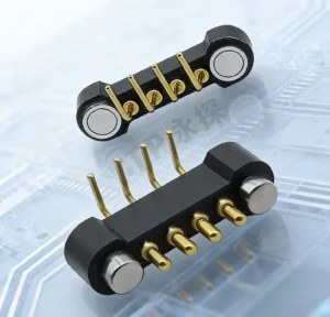
Pogo pin connectors can support selected automotive electronic interfaces
where repeated removable mating, controlled spring compliance, compact
packaging, blind docking or serviceability are important. However, a pogo
pin connector is not automatically magnetic, vibration-proof, waterproof or
suitable for every vehicle location. Automotive integration should begin
with the interface function and mounting environment, followed by mechanical
positioning, working stroke, electrical requirements, contamination,
lifecycle and system-level validation.
Pogo Pin Connectors and Magnetic Automotive Connectors Are Not the Same Thing
One of the first distinctions automotive engineers should make is between
the spring-loaded electrical contact and the complete mating architecture.
A pogo pin connector uses spring-loaded contacts to create
temporary or removable electrical paths.
A magnetic pogo pin connector adds magnets to assist
mechanical capture or retention.
Therefore, pogo pin interfaces can be designed as:- non-magnetic spring-contact arrays;
- magnet-assisted removable connectors;
- fixture or service contacts;
- docking interfaces;
- board-to-module spring-contact systems.
The electrical function comes from the conductive contacts. Magnetic force,
where used, primarily affects mechanical mating behavior.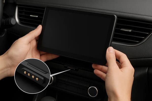
modules, docking interfaces and service connections when the mechanical
and electrical architecture is designed around the application.
Where Do Pogo Pin Connectors Fit in Automotive Electronics?
Automotive electronics do not operate in one uniform environment.

A connector behind an interior display can experience very different
mechanical, thermal and contamination conditions from a connector installed
underneath the vehicle or near a powertrain system.

This means the value of a pogo pin interface depends strongly on
where it is installed and what happens if the connection is lost.| Automotive Interface | Potential Pogo Pin Role | Main Engineering Question |
|---|---|---|
| Removable Interior Display / HMI | Power, detection and project-specific signals | Does the interface need frequent removal or blind docking? |
| Infotainment Accessory | Removable electrical module interface | How are alignment, retention and signal paths controlled? |
| Charging Cradle | Spring-loaded power and detection contacts | How are partial mating and power enable managed? |
| Service / Diagnostic Interface | Temporary electrical access | How frequently must technicians connect and disconnect? |
| Replaceable Electronic Module | Power, identification and project-specific communication | Does serviceability justify a removable interface? |
| Production Test Interface | Temporary PCB or module contact | How will repeatability and probe maintenance be controlled? |
| Safety-Critical Permanent Harness | Requires careful architecture comparison | Would a positively locked automotive connector be more appropriate? |
Benefit 1: Spring Compliance Can Support Repeatable Removable Mating
A pogo pin contains a spring-loaded plunger that can move along its intended
contact axis.

This compliance can accommodate a controlled amount of Z-axis dimensional
variation after the automotive module has been mechanically positioned.
A simplified relationship is:
S = Hfree - Hseatedwhere:
- S is actual pogo pin compression;
- Hfree is the installed free height;
- Hseated is the final contact height after mating.
This can be useful in interfaces that are connected repeatedly during
production, service or normal product use.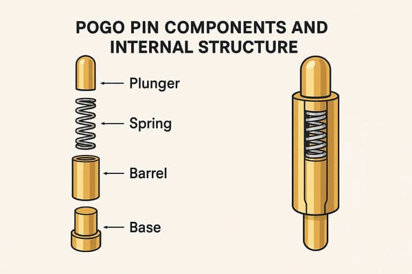
the plunger axis. Final module positioning should still be established
by the surrounding mechanical structure.
Compliance Should Not Replace Mechanical Positioning
Pogo pins should not be used as structural alignment posts or vehicle
mounting stops.

A preferred mechanical load path is:


    Vehicle Module
    →
    Housing / Guide Features
    →
    Mechanical Datum
    →
    Structural Mount
rather than:
    Vehicle Module
    →
    Pogo Pin Plunger
    →
    Spring
    →
    PCB


The connector housing should absorb the structural load while the pogo pin
maintains the defined electrical compression.
Benefit 2: Magnetic Capture Can Support Blind Docking
When magnets are added to a pogo pin interface, they can help bring two
removable modules together during the final approach.

This can be useful in vehicle interiors where:- the connector is behind a display or trim panel;
- the operator cannot easily see the mating interface;
- a removable module is returned to a fixed dock;
- service technicians need rapid repetitive connection.
A useful sequence is:


    Module Approaches
    →
    Magnetic Capture
    →
    Mechanical Guidance
    →
    Final Seating
    →
    Pogo Pin Compression
    →
    Electrical Validation
Magnetic Capture Is Not Precision Alignment
Magnetic attraction can assist approach but should not be expected to define
the final electrical position by itself.| Function | Recommended Design Element |
|---|---|
| Initial Capture | Magnets where applicable |
| Orientation | Housing geometry or mechanical coding |
| Final X-Y Position | Mechanical datums |
| Final Z Position | Mechanical stop |
| Electrical Compliance | Pogo pin working stroke |
Benefit 3: Pogo Pin Interfaces Can Support Serviceable Vehicle Modules
One important automotive benefit is not simply electrical connection—it is
the ability to define a removable module boundary.

A module may need to be:- installed late in vehicle assembly;
- removed for service;
- replaced without disturbing a larger wiring assembly;
- connected temporarily during diagnostics;
- offered in multiple vehicle configurations.
A spring-contact interface can support these architectures when the expected
mating frequency and environmental conditions justify a removable
connection.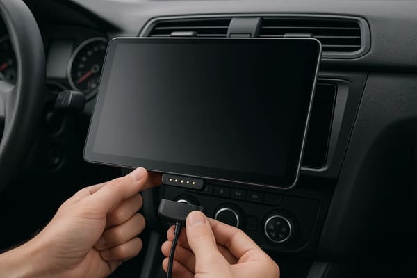
module positioning and electrical interface design can be evaluated
together.
A Removable Module Needs an Interface Contract
The connector should be designed from the functions that cross the module
boundary.| Interface Layer | Questions to Define |
|---|---|
| Mechanical | How is the module positioned, retained and removed? |
| Power | What voltage and current cross the interface? |
| Detection | How does the system know that the module is correctly seated? |
| Identification | Does the vehicle need to identify the module variant? |
| Signals | Which control or communication paths are required? |
| Environment | What happens when the interface is exposed or unmated? |
| Service | Which side should be replaceable if the contact surface wears? |
Benefit 4: A Shallow Interface Can Create Packaging Freedom
Pogo pins can contact relatively flat target surfaces without requiring the
same insertion depth as some plug-and-receptacle structures.

This may be useful in vehicle interiors where designers are working around:- display thickness;
- instrument-panel depth;
- battery or PCB placement;
- trim surfaces;
- speaker structures;
- thermal components;
- mechanical mounting points.
Low Profile Does Not Mean Zero Packaging Volume
The complete interface still requires room for:- pogo pin body;
- working stroke;
- mating target;
- PCB routing;
- termination;
- housing structure;
- mechanical guidance;
- magnets where used.
Engineers should therefore compare complete three-dimensional connector
envelopes rather than visible connector height alone.
Benefit 5: Custom Pin Maps Can Combine Multiple Vehicle Functions
A custom pogo pin array can allocate independent contacts according to the
actual electronic-module requirements.
Possible functions include:
- power;
- power return;
- module detection;
- module identification;
- project-specific control signals;
- project-specific communication paths;
- diagnostic or service functions.
This is useful for custom modules because the electrical interface can be
developed around the vehicle subsystem instead of forcing the design into
one fixed connector Pin Map.
Pin Count Does Not Prove Automotive Data Compatibility
A connector with more pogo pins simply provides more conductive paths.

It does not automatically prove compatibility with CAN, LIN, Automotive
Ethernet, camera signals or another vehicle communication system.
Signal performance can depend on:
- signal and reference allocation;
- contact geometry;
- contact pitch;
- PCB transitions;
- cable or FPC architecture;
- return-path continuity;
- crosstalk;
- complete-channel length.
Protocol compatibility should therefore be evaluated at the complete
electrical-channel level.
Benefit 6: Spring Contacts Can Simplify Temporary Test and Service Access
Automotive electronics require manufacturing test, programming,
diagnostics and service access at different stages of the product
lifecycle.

Pogo pins can be useful because they create temporary electrical connections
without permanently adding a user-facing receptacle to every test point.
Possible uses include:
- PCB programming;
- end-of-line functional testing;
- module diagnostics;
- production fixtures;
- service tools;
- temporary calibration interfaces.
In these cases, pogo pin repeatability, fixture alignment, target wear and
maintenance may be more important than magnetic attachment.
Benefit 7: The Contact Interface Can Be Designed as a Replaceable Wear Element
In some removable automotive architectures, it can be useful to separate the
replaceable contact surface from the more expensive electronic module.

For example, a docking contact, cable assembly or service-side target may be
easier to replace than an entire infotainment or control module.

This does not automatically reduce maintenance cost, but it gives the
product architect another way to define the service strategy.
Do Pogo Pins Provide Better Vibration Resistance?
This needs a more careful answer than “yes.”

Spring-loaded contacts can maintain axial compliance while the surrounding
mechanical structure moves within its intended range.

However, the pogo pin should not be used as the product's vibration
isolator.

Connection stability under vehicle vibration can also depend on:- housing retention;
- module mass;
- mounting location;
- contact force;
- working stroke;
- target flatness;
- resonance of the surrounding structure;
- cable or harness loading.
The correct claim is therefore:


    Pogo pin compliance can contribute to a stable removable interface, but
    automotive shock and vibration performance must be validated at the
    complete assembly level.
Automotive Environment Depends on Mounting Location
“Automotive grade” should not be treated as one universal environmental
condition.

The connector requirements can change significantly depending on whether
the interface is installed:- inside the passenger compartment;
- behind an instrument panel;
- inside a door or seat;
- inside a trunk or cargo area;
- near the chassis;
- inside a powertrain environment;
- outside the protected vehicle enclosure.
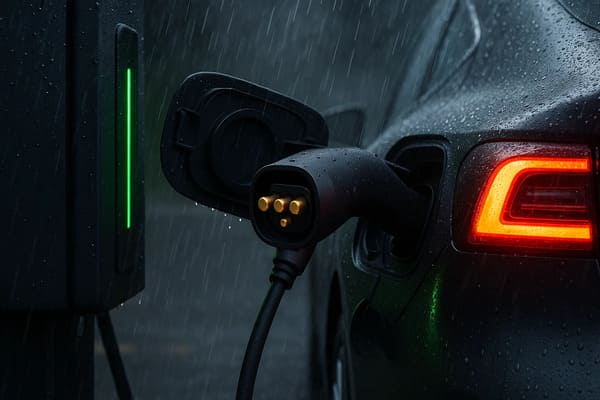
mounting location and complete electronic-module application rather than
a generic “automotive grade” label.
Environmental Validation Is More Than an IP Rating
Depending on location, an automotive interface may need evaluation for:- temperature exposure;
- temperature cycling;
- mechanical vibration and shock;
- humidity or condensation;
- dust;
- water exposure;
- road contaminants;
- oils or cleaning chemicals;
- salt-containing environments where relevant.
A flat pogo pin target does not automatically create an IP68 interface.

Environmental protection depends on the complete sealing boundary,
including the connector feedthrough, housing, target, PCB or wire
termination, gaskets and surrounding enclosure.
ISO 16750 Provides a Useful Automotive Environmental Framework
The ISO 16750 series addresses environmental conditions and testing for
electrical and electronic equipment in road vehicles.

Relevant parts include electrical loads, mechanical loads, climatic loads
and chemical loads.

The applicable test profile should be selected according to the actual
vehicle component and mounting location rather than copied directly from an
unrelated automotive application.

Official references:-
ISO 16750-1:2023 — General
-
ISO 16750-2:2023 — Electrical loads
-
ISO 16750-3:2023 — Mechanical loads
-
ISO 16750-4:2023 — Climatic loads
-
ISO 16750-5:2023 — Chemical loads
EMC Must Be Evaluated Separately
Pogo pin spring compliance does not inherently reduce electromagnetic
interference.

Likewise, a metal connector housing should not automatically be described as
an EMI shield.
Automotive signal integrity and EMC can depend on:
- signal-return architecture;
- ground contact placement;
- PCB layout;
- cable shielding;
- housing continuity;
- vehicle grounding architecture;
- frequency range;
- complete system configuration.
EMC requirements should therefore be evaluated separately from the
mechanical connector design.
High Current Requires Complete-Path Thermal Validation
A pogo pin can form one part of a vehicle power connection, but contact
diameter alone does not determine current capability.
A simplified path is:
    Vehicle Power Source
    →
    PCB / Wire
    →
    Termination
    →
    Pogo Pin
    →
    Contact Interface
    →
    Target
    →
    Electronic Module
The complete resistance can be represented as:
    Rpath =
    Rsource +
    Rtermination +
    Rpogo +
    Rinterface +
    Rtarget +
    Rmodule
The voltage drop is:
Vdrop = I × Rpathand resistive loss is:
Ploss = I² × Rpath

Current capability should therefore be validated using the intended working
stroke, target condition, wiring structure, duty cycle and ambient
temperature.
Parallel Pogo Pins Do Not Automatically Share Current Equally
Multiple contacts can be connected in parallel, but branch current may vary
because of:- contact-resistance differences;
- working-stroke variation;
- module tilt;
- target flatness;
- PCB routing;
- termination resistance.
A high-current automotive array should therefore be evaluated as a complete
electrical and thermal system.
A Make-First Contact Does Not Prevent Electrical Arcing by Itself
Staggered contact heights can provide useful information about connection
sequence.

For example, a pilot or detection contact may engage before the main power
contacts.

However, that contact does not physically suppress an arc by itself.

The control system must use the connection-state information to manage the
main electrical path.
A possible controlled sequence is:
    Module Approaches
    →
    Mechanical Seating
    →
    Pilot / Detection Contact
    →
    Connection Validated
    →
    Main Power Enabled
During removal:
    Main Power Disabled
    →
    Electrical State Confirmed
    →
    Main Contacts Separate
    →
    Module Removed
Partial Mating Must Be Treated as an Electrical State
| Condition | Possible Effect | Engineering Response |
|---|---|---|
| One Contact Engages First | Unexpected electrical sequence | Pin Map and power-control review |
| Module Is Tilted | Unequal pogo pin compression | Mechanical guidance |
| Only Some Parallel Contacts Engage | Current concentration | Connection validation before power enable |
| Debris Prevents Seating | Higher or unstable resistance | Contamination detection and maintenance |
| Module Separates Under Load | Transient or arcing risk | Controlled power shutdown |
Safety-Related Automotive Electronics Need System-Level Analysis
A pogo pin connector should not independently be described as making an
automotive system functionally safe.

If a connection is part of a safety-related electrical or electronic
function, the system engineering process should define:- the consequence of connection loss;
- fault detection;
- diagnostic coverage where required;
- safe-state behavior;
- connector degradation assumptions;
- system-level validation.
ISO 26262 addresses functional safety of safety-related E/E systems in
series-production road vehicles. Applicability and safety requirements are
determined at the vehicle/system level rather than by the connector alone.
IATF 16949 Is a Quality-System Requirement, Not a Connector Rating
Automotive sourcing teams may require suppliers to operate under automotive
quality-management requirements such as IATF 16949 and customer-specific
requirements.

This should not be confused with connector performance qualification.

IATF 16949 addresses organizational quality-management processes. Individual
connector characteristics still need approved drawings, process controls,
validation plans and customer-specific acceptance criteria.

A supplier should only claim IATF 16949 certification when the applicable
manufacturing organization and scope are covered by a valid certification.
When Should Engineers Consider Pogo Pins in Automotive Electronics?
| Requirement | Pogo Pin Suitability |
|---|---|
| Frequent Removable Connection | Often worth evaluating |
| Blind Docking | Useful, especially with controlled mechanical guidance |
| Compact Interior Module | Can provide packaging flexibility |
| Service / Diagnostic Contact | Strong use case |
| Production Test Interface | Strong use case |
| Replaceable Electronic Module | Potentially useful |
| Permanent Safety-Critical Harness | Compare carefully with positively locked automotive connectors |
| Unprotected Underbody Interface | Requires substantial environmental qualification |
| High-Voltage Traction Connection | Requires system-specific architecture; do not infer suitability from pogo pin construction |
When May a Conventional Automotive Connector Be Better?
Pogo pin connectors should not be treated as universal replacements for
sealed, locked automotive harness connectors.
A conventional connector may remain preferable when:
- the connection is intended to remain permanently mated;
- positive locking is required;
- standardized automotive harness compatibility is important;
- very high contact density is required;
- the mounting environment is extremely exposed;
- a proven standardized high-speed automotive interface is preferred;
- frequent removable mating provides little system benefit.
Recommended Automotive Pogo Pin Validation Plan
| Validation Area | Recommended Evaluation |
|---|---|
| Mounting Location | Define the actual vehicle environment first |
| Working Stroke | Verify minimum, nominal and maximum compression |
| Mechanical Alignment | Evaluate X-Y-Z and angular tolerance |
| Vibration / Shock | Validate the complete mounted assembly |
| Contact Resistance | Measure under defined stroke and target conditions |
| Power Path | Measure complete-path voltage drop and temperature rise |
| Current Sharing | Evaluate parallel contacts where used |
| Partial Mating | Test tilted and incomplete connection states |
| Signal Channel | Validate the complete channel for the intended communication system |
| Temperature | Evaluate the actual component mounting environment |
| Humidity / Water | Evaluate mated and unmated interface conditions |
| Chemical Exposure | Evaluate application-relevant fluids and materials |
| Contamination | Evaluate representative dust and metallic debris where relevant |
| Lifecycle | Reproduce actual mating, electrical load and environmental conditions |
Information Required for an Automotive Connector Engineering Review
| Project Input | Information to Provide |
|---|---|
| Vehicle Application | Infotainment, HMI, charging dock, service interface, module or another function |
| Mounting Location | Passenger compartment, seat, door, trunk, exterior or another defined location |
| Connection Function | Power, signal, detection, identification, service or test |
| Pin Map | Function of every electrical contact |
| Electrical Conditions | Voltage, continuous current and peak current |
| Signal Requirement | Protocol, data rate and channel requirements where applicable |
| Working Stroke | Minimum, nominal and maximum pogo pin compression |
| Mechanical Tolerance | X-Y-Z and angular mating variation |
| Retention | Normal seated holding requirement |
| Environment | Temperature, vibration, water, humidity, dust and chemical exposure |
| Safety Relevance | Expected system response if the connection is lost |
| Lifecycle | Expected mating frequency and end-of-life criteria |
| Project Files | 2D drawing, 3D vehicle/module assembly, PCB layout or interface specification |
Frequently Asked Questions
What are the main benefits of pogo pin connectors in automotive electronics?
They can provide spring compliance, fast removable mating, blind docking,
compact module interfaces, customizable electrical paths and convenient
test or service access when the vehicle application is suitable.
Are automotive pogo pin connectors always magnetic?
No. Pogo pins are spring-loaded electrical contacts. Magnets can be added
for capture and retention, but non-magnetic pogo pin interfaces are also
widely possible.
Are pogo pin connectors better for automotive vibration?
Not automatically. Spring compliance can support electrical contact, but
shock and vibration performance depends on the complete housing, mounting,
working stroke, retention and module structure.
Can pogo pins be used in automotive infotainment systems?
They can be evaluated for removable displays, docks and project-specific
HMI modules where the mechanical and electrical requirements suit a
spring-contact interface.
Are automotive pogo pin connectors IP68 waterproof?
Not automatically. Ingress protection depends on the complete connector,
feedthrough, housing, seals, target and tested assembly configuration.
Can pogo pins carry high automotive current?
They can form part of a higher-current interface, but capability depends on
complete-path resistance, working stroke, target condition, termination,
current sharing and temperature rise.
Can pogo pin connectors carry CAN or Automotive Ethernet?
Potentially, but protocol capability cannot be inferred from pin count.
Signal and return architecture, contact geometry, PCB transitions and the
complete electrical channel must be validated.
Does a make-first pogo pin prevent arcing?
No. A staggered pilot contact can provide connection-state information, but
the electrical system must use that information to disable or enable the
main power path at the appropriate time.
Are pogo pins suitable for safety-critical automotive electronics?
Suitability depends on the system function, failure consequences,
architecture, diagnostics and validation. A connector should not be assumed
functionally safe based only on its mechanical structure.
Does IATF 16949 certify an automotive pogo pin connector?
No. IATF 16949 concerns the automotive quality-management system of the
relevant organization and scope. Connector performance still requires
project-specific specifications and validation.
What automotive environment should a pogo pin connector be tested for?
The test profile should be derived from the actual vehicle mounting
location and electrical function, including relevant mechanical, climatic,
electrical and chemical stresses.
When should a conventional automotive connector be used instead?
A conventional locked connector may be preferable for permanent harness
connections, standardized vehicle interfaces, very exposed environments or
applications where removable mating provides little engineering benefit.
Request an Automotive Pogo Pin Connector Engineering Review
Review

    pogo pin and spring-contact solutions

for removable automotive electronic modules, service interfaces and
project-specific electrical contacts.

For magnet-assisted removable interfaces, explore

    custom magnetic connector solutions
.

Submit the vehicle application, mounting location, Pin Map, voltage,
current, signal requirements, working stroke and mechanical drawings through
the

    Get Quote & Samples page
.


    CTP can review pogo pin layout, working stroke, mating targets,
    mechanical alignment, magnetic capture where required, PCB, FPC or wire
    termination and project-specific validation requirements for automotive
    electronic interfaces. Final vibration performance, temperature range,
    current capability, communication performance, ingress protection,
    lifecycle and automotive qualification depend on the approved design,
    vehicle mounting location and complete system validation.
CTP ENGINEERING PATHS
Choose the right path for your project
Move from application requirements to a connector pair, a data-capable cable assembly, or a charging cable configuration. Final specifications are confirmed against an approved drawing and project validation plan.
Magnetic Connectors
Connector geometry, pin layout, mechanical integration and OEM/ODM review.
Engineering overview → 02Magnetic Data Cables
Power and signal allocation, cable exit, interface selection and assembly review.
Cable engineering → 03Magnetic Charging Cables
Browse the complete cable catalog and shortlist a starting structure for customization.
View cable catalog →