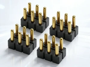
A magnetic power connector should not be selected from a current rating, pin count, or magnetic force alone. The connector is only one section of a complete DC power path that begins at the source and continues through conductors, terminations, spring-loaded contacts, mating surfaces, device-side wiring or PCB structures, and the return path.
For that reason, a magnetically attached interface is not automatically a valid full-power connection. The electrical engineer still has to control installed contact compression, total path resistance, voltage drop, temperature rise, contact allocation, partial-mating behavior, and the conditions under which the system is allowed to energize the load.
This guide focuses on conductive magnetic power connectors used for removable low-voltage DC interfaces. It does not cover inductive wireless charging or attempt to define a universal current, voltage, temperature, or lifecycle rating.
What Is a Magnetic Power Connector?
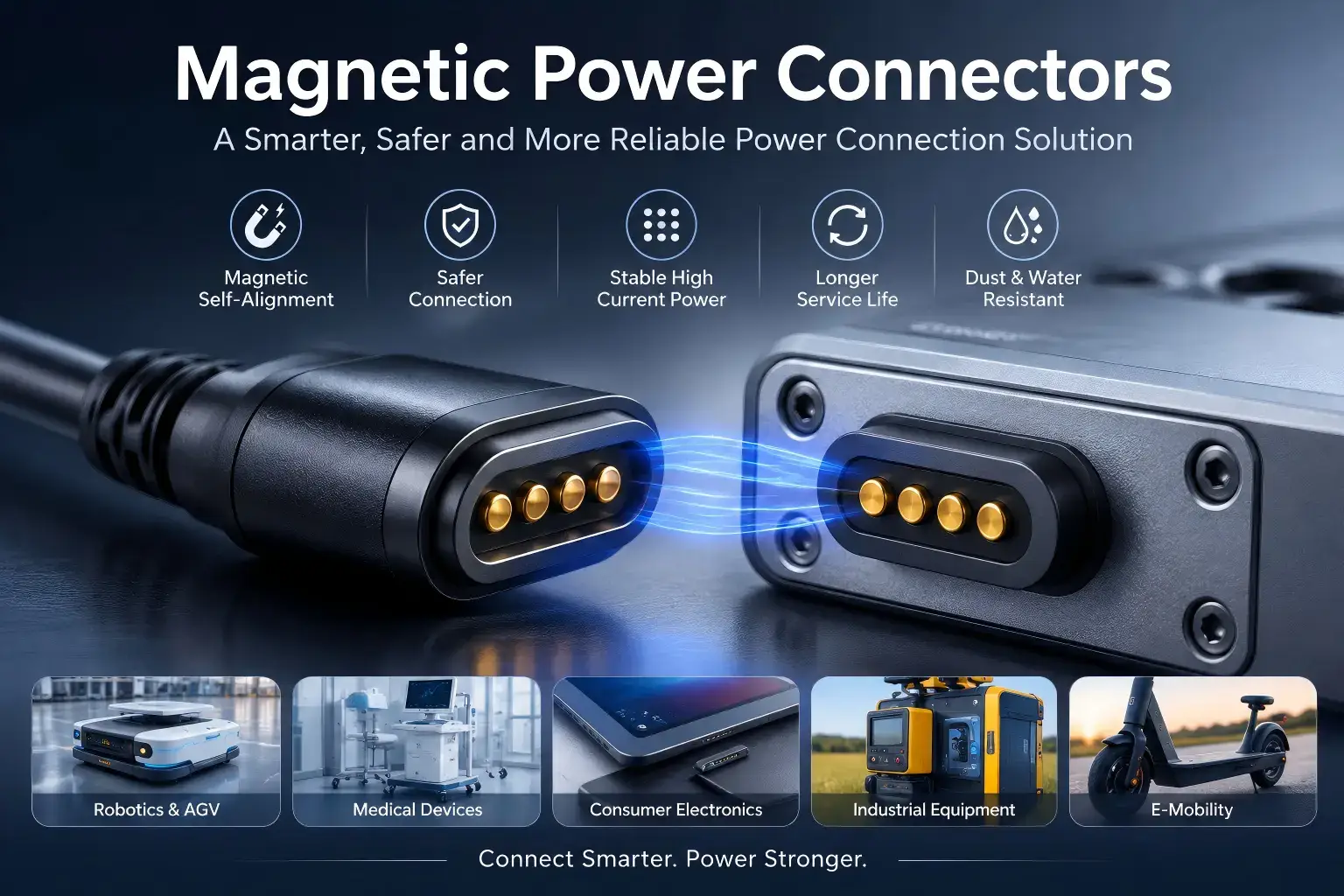
A magnetic power connector is a removable electrical interface in which magnetic attraction assists capture or retention while dedicated conductive contacts transfer electrical power between two mating assemblies.
In a typical spring-loaded architecture, the different parts of the interface perform different functions:
| Function | Typical Design Element |
|---|---|
| Initial capture | Magnetic system |
| Final alignment | Housing, guides and mechanical datums |
| Final seated position | Mechanical stops and product stack-up |
| Electrical compliance | Spring-loaded pogo contacts |
| Power transfer | Power contacts, mating targets, conductors and terminations |
| Connection-state control | System electronics where required |
The distinction matters because magnetic attraction is a mechanical condition. Power delivery is an electrical and thermal condition.
Magnetic attachment does not automatically mean the interface is ready to carry full power.
Start with the Power Requirement, Not the Connector Rating
Before selecting a magnetic power connector, define what the complete device actually requires.
The minimum electrical input should include:
- source voltage and allowable variation;
- minimum acceptable voltage at the load;
- continuous operating current;
- peak current;
- peak duration and repetition;
- duty cycle;
- allowable voltage drop;
- ambient and enclosure thermal conditions;
- expected mating and operating state.
This immediately separates two different engineering questions.
Connector question: Can the contact interface operate under the required electrical and mechanical condition?
System question: Can the complete source-to-load path deliver the required power without exceeding the project’s electrical or thermal limits?
A current value printed on a component drawing cannot answer the second question by itself.
Map the Complete Current Path from Source to Load
Current capability should be evaluated through the complete electrical loop.
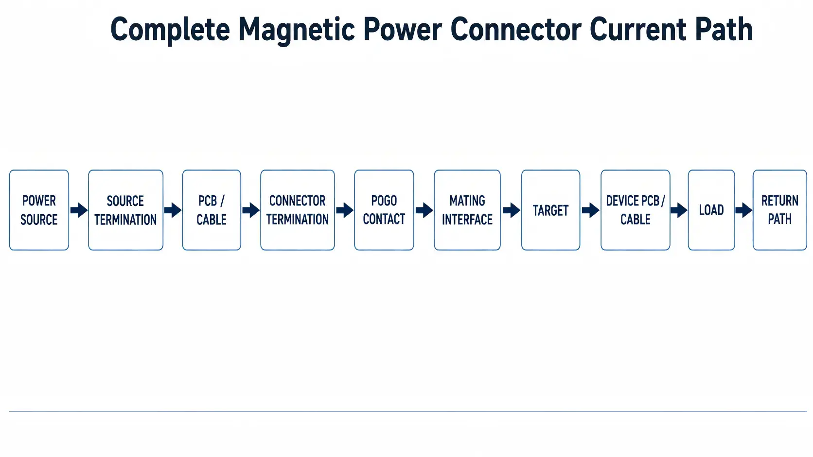
A simplified magnetic power path may be represented as:
Power source → source termination → wire or PCB → connector termination → pogo contact → mating interface → target contact → device PCB or wire → load → return path
Each section contributes resistance.
A useful system model is:
Rpath = Rsource + Rtermination + Rconductor + Rpogo + Rinterface + Rtarget + Rdevice + Rreturn
The equation is not intended to prescribe a universal connector resistance. Its purpose is to prevent the engineering team from optimizing one contact while ignoring a higher-resistance cable termination, PCB trace, solder joint, mating target, or return path.
This creates an important troubleshooting rule:
High path resistance → higher voltage drop → higher I²R loss → possible local temperature rise.
The highest-risk point is not necessarily the pogo pin itself.
How Should Power Be Allocated Across the Contacts?
Pin count should follow the required circuit functions rather than a preferred connector appearance.
Dedicated Supply and Return
A simple power-only interface may use one dedicated supply path and one dedicated return path.
This architecture can be appropriate when each contact and every upstream and downstream conductor can operate within the approved electrical, thermal, and mechanical conditions.
Parallel Power Contacts
Multiple contacts can be assigned in parallel when the architecture requires additional current-path capacity or redundancy, but engineers should not assume equal current distribution.
Current sharing can be affected by differences in:
- contact resistance;
- installed working stroke;
- target flatness;
- termination resistance;
- PCB or conductor routing;
- contamination;
- temperature.
This means:
Two parallel contacts do not automatically provide exactly twice the usable current capability of one contact.
The parallel group should be evaluated as an assembled electrical network under the defined operating condition.
Power Plus Detection or Control
A multi-contact magnetic interface may reserve additional contacts for detection, identification, control, or another project-specific function.
This can be useful when the system needs to distinguish between:
- no connector present;
- partial contact;
- mechanically seated;
- validated accessory or module;
- power-enabled state.
Whether those states are required depends on the system architecture. They should not be added automatically to every connector.
Why Working Stroke Affects the Electrical Interface
Spring-loaded contacts operate correctly only when the assembled product places them within the intended working-compression window.
Working stroke is not the same as total pogo-pin travel.
The installed compression depends on the complete mechanical stack-up, which may include:
- pogo pin free height;
- connector body position;
- PCB or FPC position;
- target height;
- housing dimensions;
- mechanical-stop position;
- seal compression;
- assembly tolerance;
- structural deflection.
The electrical engineer should therefore review minimum, nominal, and maximum installed compression rather than validating only a nominal CAD position.
If the connector is under-compressed, the interface may become more sensitive to movement, surface condition, contamination, and tolerance variation.
If the connector is over-compressed, spring reaction and mechanical load can increase, potentially affecting the pogo pin, target, PCB, housing, or magnetic retention balance.
The pogo contacts should provide controlled electrical compliance. They should not serve as the structural stop for the complete product.
Voltage Drop and I²R Loss Must Be Evaluated Across the Complete Path
Once the complete path resistance is understood, two fundamental relationships become useful.
Vdrop = I × Rpath
and:
Ploss = I² × Rpath
Voltage drop matters because the load does not receive the source voltage directly. It receives the source voltage minus losses in the supply path.
The design process should therefore start with a voltage budget:
Source voltage → allowable path loss → minimum required load voltage
Power loss is even more important as current increases because resistive heating is proportional to the square of current.
This does not mean that every magnetic connector operating at higher current will overheat. It means that resistance which was insignificant at one operating condition may become important at another.
The correct question is not:
“How many amps can this pogo pin carry?”
It is:
“What voltage drop and temperature rise does the complete installed path produce at the defined current, duty cycle and ambient condition?”
Current Capability Is Ultimately a Thermal Question
Electrical resistance creates heat, but the final connector temperature also depends on how effectively the assembly can reject that heat.
Important variables can include:
- continuous versus intermittent load;
- peak-current duration;
- duty cycle;
- ambient temperature;
- connector housing geometry;
- PCB copper and conductor size;
- wire length and structure;
- contact allocation;
- termination design;
- enclosure airflow or lack of airflow;
- heat generated by nearby components.
This is why a current number should not be transferred automatically from an isolated pogo pin to a finished magnetic connector or cable assembly.
IEC 60512-5-1 provides a standardized method for connector temperature-rise testing at a specified current under defined conditions. IEC 60512-5-2 addresses current-temperature derating at elevated ambient temperature.
These test methods support the validation process, but they do not define the project-specific current rating or acceptance temperature. Those limits must come from the approved product requirement and relevant component or system constraints.
What Happens During Partial Mating?
A magnetic power connector does not transition instantaneously from disconnected to closely seated.
The real sequence may include:
Approach → magnetic capture → first contact → partial compression → final mechanical seating → electrical validation → power-enabled state
This creates an engineering question that is especially important for power interfaces:
What electrical state is allowed before the connector is fully seated?
Depending on the product, partial mating can create conditions such as:
- one power contact touching before the return contact;
- an offset contact touching the wrong target area;
- electrical continuity before full working stroke is reached;
- connection and disconnection while load current is flowing;
- charging of downstream capacitance when contact is first established;
- energized exposed contacts while the mating half is absent.
The severity of these conditions depends on voltage, current, source impedance, downstream circuitry, inductive or capacitive load behavior, contact geometry, and the system protection architecture.
Therefore, the design team should explicitly define the allowed states rather than assume the magnet solves the electrical transition.
Possible State-Control Methods
Where required by the system, state control may include:
- a dedicated detection contact;
- accessory identification;
- contact sequencing;
- current limiting;
- precharge or inrush control;
- controller-based power enable;
- fault detection;
- polarity or orientation control.
These are system-level options rather than universal magnetic-connector requirements.
Magnetic Retention Does Not Define Electrical Power Capability
A stronger magnet does not automatically create a better power connection.
The magnetic system mainly contributes to capture and retention. The electrical interface still depends on contact geometry, installed compression, surface condition, conductor design, termination quality, and the complete power path.
A simplified seated-force model can be useful:
Available retention margin ≈ magnetic attraction − spring reaction − other separating loads
Other loads may include seal compression, cable force, vibration, housing deformation, or external disturbance.
Increasing magnetic attraction may improve holding margin, but it can also increase removal force, closing impact, structural load, and attraction of ferromagnetic debris.
The design target is therefore not maximum magnetic force.
It is sufficient capture and retention while preserving the required seating, removal behavior, working stroke, and environmental tolerance.
Common Magnetic Power Connector Failure Modes
| Failure Condition | Possible Mechanism | Engineering Check |
|---|---|---|
| Excessive voltage drop | High resistance in contacts, conductors, terminations, PCB paths, or return path | Measure the complete path under defined current |
| Local temperature rise | I²R loss concentrated at a resistive transition | Measure temperature at representative path locations |
| Under-compressed contact | Tolerance stack reduces installed pogo working stroke | Calculate and verify minimum compression |
| Over-compressed contact | Mechanical stop or stack-up produces excessive stroke | Verify maximum compression and structural load |
| Unequal current sharing | Parallel contacts have different effective path resistance | Evaluate individual path behavior where practical |
| Intermittent power | Movement, contamination, inadequate seating, wear, or contact disturbance | Monitor continuity or resistance under representative disturbance |
| Partial-mating fault | Power becomes active before the intended seated state | Evaluate every credible mating position |
| Termination heating | Crimp, solder, weld, PCB joint, or cable section becomes the path bottleneck | Include terminations in electrical and thermal measurements |
| Debris-related seating problem | Foreign material prevents full mechanical engagement | Inspect working stroke and interface condition after exposure |
| Cable-related failure | Cable movement or strain transfers load into the connector or termination | Validate strain relief and representative cable loading |
The important point is that “connector failure” may originate outside the visible contact interface.
For example:
Weak termination → increased path resistance → higher I²R loss → local heating → further electrical drift.
Another possible chain is:
Contamination → incomplete seating → reduced working stroke → unstable contact condition → resistance variation → voltage disturbance.
How to Validate a Magnetic Power Connector
A useful validation structure is:
Requirement → Test Condition → Measurement → Acceptance Criterion → Post-Test Check
| Requirement | Representative Condition | Measurement |
|---|---|---|
| Acceptable power delivery | Defined continuous and peak load | Complete-path voltage drop |
| Electrical contact quality | Defined working stroke and mated state | Contact or path resistance |
| Thermal performance | Specified current, duty cycle and ambient condition | Temperature rise after stabilization |
| Tolerance robustness | Minimum, nominal and maximum assembled compression | Resistance, continuity and seating condition |
| Dynamic stability | Representative movement or vibration | Contact disturbance or resistance variation |
| Partial-mating behavior | Credible approach and release positions | Contact sequence and electrical state |
| Lifecycle stability | Project-defined mating duty | Electrical and mechanical drift before and after cycling |
Relevant IEC 60512 connector test methods include temperature rise, current-temperature derating, contact resistance, and contact-resistance variation under specified dynamic conditions.
The standards provide test methods. The project must still define the sample configuration, operating condition, severity, measurement location, and acceptance limits.
Engineers developing a complete qualification program can continue with CTP’s magnetic pogo pin connector validation guide.
When a Magnetic Power Connector May Not Be the Right Architecture
A magnetic power interface is useful when removable connection, low insertion effort, docking, frequent mating, or controlled breakaway creates meaningful product value.
Another connector architecture may be more appropriate when:
- a positive mechanical lock must remain engaged under substantial external load;
- a standardized interoperable power connector already satisfies the project;
- the electrical system cannot tolerate an exposed or partially mated contact state;
- the required voltage, power level, spacing, insulation, or regulatory framework is better served by an established connector family;
- the connection is effectively permanent;
- uncontrolled conductive or ferromagnetic contamination is present;
- magnetic capture adds complexity without solving a real mating problem.
The correct architecture decision should therefore begin with the product interface duty rather than with the appeal of magnetic mating itself.
What to Define Before Requesting Engineering Review
For a magnetic power connector project, useful engineering inputs include:
- source voltage and allowable range;
- minimum required voltage at the device;
- continuous current;
- peak current, duration and repetition;
- duty cycle;
- required Pin Map;
- whether contacts are dedicated or paralleled for power;
- available connector X, Y and Z space;
- mechanical stop and installed working-stroke concept;
- PCB, FPC, wire, or cable architecture;
- cable length where applicable;
- mating and separation direction;
- whether exposed contacts can be energized;
- required detection or power-enable behavior;
- operating environment;
- project-specific validation requirements;
- available 2D or 3D drawings.
Engineers can browse CTP’s magnetic connector structures when evaluating available component architectures.
Projects specifically involving higher current and complete cable assemblies can continue with the high-current magnetic cable solution guide.
If the project is still comparing a conventional two-pole power connector with a removable magnetic architecture, see the 2-pin DC power connector guide.
Frequently Asked Questions About Magnetic Power Connectors
What is a magnetic power connector?
A magnetic power connector is a conductive electrical interface in which magnets assist capture or retention while dedicated contacts carry power. The magnet and the electrical current path perform different functions.
Are magnetic power connectors the same as wireless chargers?
No. The magnetic power connectors discussed here use physical conductive contacts. Magnetic attraction assists mating, but current still flows through a wired electrical path.
How much current can a magnetic power connector carry?
There is no universal current value for the architecture. Usable current depends on the contacts, working stroke, conductor and termination structure, contact allocation, duty cycle, ambient condition, allowable voltage drop, and temperature-rise validation.
Can two pogo pins in parallel carry twice the current?
That should not be assumed. Parallel contacts can have different effective resistance because of mechanical, electrical, thermal, and manufacturing variation. The assembled parallel path should be validated under the intended operating conditions.
Does a stronger magnet reduce contact resistance?
Not directly. The pogo spring and installed compression establish local contact force, while mechanical datums control seating. Magnetic force mainly affects capture and retention of the complete interface.
Why does working stroke matter for power delivery?
Working stroke affects the installed contact condition. Insufficient or excessive compression can reduce mechanical margin or increase structural load, so minimum, nominal, and maximum assembled conditions should be reviewed.
How should magnetic connector voltage drop be calculated?
Start with the complete source-to-load and return path rather than only the contact. The basic relationship is Vdrop = I × Rpath, where Rpath includes the relevant conductors, terminations, contacts, mating interfaces, and return connections.
Why does temperature rise matter when selecting current?
Resistive power loss increases with I²R. The final temperature also depends on duty cycle, ambient condition, conductor design, enclosure structure, and heat rejection, so current capability should be validated thermally under defined conditions.
Should magnetic power contacts be energized while disconnected?
That is a system-level design decision. Engineers should evaluate exposed-contact risk, partial mating, polarity, load behavior, and the intended user or machine interaction before deciding whether detection, current limiting, sequencing, or controlled power enable is required.
How should a magnetic power connector be validated?
Define requirements first, then test the relevant assembled conditions for voltage drop, resistance, temperature rise, mating-state behavior, tolerance, dynamic stability, and lifecycle performance. Acceptance limits should come from the approved project specification.
Engineering Reference Sources
- IEC 60512-5-1 — Temperature Rise
- IEC 60512-5-2 — Current-Temperature Derating
- IEC 60512-2-2 — Contact Resistance
- IEC 60512-2-3 — Contact Resistance Variation
Request a Magnetic Power Interface Review
If your project uses a removable magnetic interface for charging or DC power delivery, provide the source voltage, continuous and peak current, duty cycle, Pin Map, connector space, working-stroke stack-up, PCB or cable structure, mating direction, electrical state during partial mating, environmental conditions, and available drawings.
Submit Your Magnetic Power Connector Project for Engineering Review
CTP ENGINEERING PATHS
Choose the right path for your project
Move from application requirements to a connector pair, a data-capable cable assembly, or a charging cable configuration. Final specifications are confirmed against an approved drawing and project validation plan.
Magnetic Connectors
Connector geometry, pin layout, mechanical integration and OEM/ODM review.
Engineering overview → 02Magnetic Data Cables
Power and signal allocation, cable exit, interface selection and assembly review.
Cable engineering → 03Magnetic Charging Cables
Browse the complete cable catalog and shortlist a starting structure for customization.
View cable catalog →