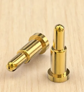
Engineering Summary:
A micro pogo pin connector can provide a compact conductive interface between a smart ring and its charging cradle, case or service fixture. However, the connector should not be selected only by pogo pin diameter, magnetic force or external thickness. The complete design must coordinate ring size, enclosure curvature, battery and sensor packaging, contact position, working stroke, cradle geometry, exposed-contact state, contamination, user handling and charging-system protection.
A micro pogo pin connector can provide a compact conductive interface between a smart ring and its charging cradle, case or service fixture. However, the connector should not be selected only by pogo pin diameter, magnetic force or external thickness. The complete design must coordinate ring size, enclosure curvature, battery and sensor packaging, contact position, working stroke, cradle geometry, exposed-contact state, contamination, user handling and charging-system protection.
Smart rings combine sensing, processing, wireless communication and battery power inside a circular body-worn enclosure. Unlike a smartwatch, a ring provides no large flat back surface for a conventional charging connector.The charging interface must compete for space with the battery, optical sensors, motion sensors, antenna, circuit board, internal supports and skin-contact surfaces. Its position also changes with the ring size and the geometry of the charging cradle.
A spring-loaded contact interface may provide a compact charging path and compensate for a defined amount of mechanical variation. Magnetic capture may assist the final docking movement. Neither function removes the need for mechanical location, electrical protection and complete product validation.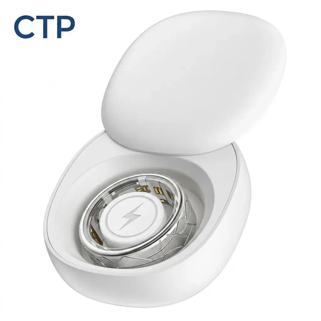
Smart Ring Charging Is a System Packaging Problem
The visible contact points are only a small part of the charging system. Engineers must allocate space for the entire conductive and mechanical path.| Packaging Area | Function | Possible Conflict |
|---|---|---|
| External charging surface | Provides the mating targets or exposed contacts | Skin contact, optical sensors, cosmetic finish and ring curvature |
| Internal termination | Connects the target or pogo pin to the PCB or flexible circuit | Battery, antenna, sensing components and structural supports |
| Magnetic structure | Assists capture or retention in the charger | Sensor position, antenna performance, internal magnetic parts and available wall thickness |
| Mechanical locating feature | Defines final position and orientation | Ring size variation, charger insert and removal access |
| Charging-case contacts | Provide compliant contact against the ring | Case dimensions, replaceability, contamination and assembly access |
| Cleaning clearance | Allows users to inspect and clean the interface | Deep recesses, narrow slots and decorative structures |
A connector that appears thin in a product photograph may still require additional internal depth for its termination, insulation, magnetic components, mechanical stop and supporting structure.Choose the Charging Architecture Before Choosing the Pogo Pin
A smart ring can use several charging architectures. The correct structure depends on the product enclosure, battery system, user routine and manufacturing strategy.| Charging Architecture | How It Works | Primary Engineering Focus |
|---|---|---|
| Charging cradle with pogo pins | Spring-loaded contacts are installed in the cradle and mate with flat targets on the ring | Ring-size fit, target position, working stroke, cleaning and contact replaceability |
| Charging case with pogo pins | The ring is positioned inside a protected case containing charging contacts | Case insertion, orientation, lid pressure, portable charging and contamination control |
| Magnetic cable or charging puck | A detachable accessory connects directly to the ring | Cable weight, ring movement, side load, release direction and user handling |
| Contactless charging | Energy transfers without an exposed conductive charging interface | Coil packaging, alignment, thermal behavior, charging efficiency and control electronics |
| Service-only spring contacts | Temporary contacts are used during production, testing or repair | Fixture access, repeatability, replaceability and separation from consumer charging |
A contact-based interface may reduce the need to install a charging coil inside the ring, but it introduces exposed-contact, alignment and contamination requirements.

Contactless charging removes exposed conductive targets but requires space for the coil and associated charging electronics. Neither architecture is universally smaller or more efficient without a complete product comparison.
Ring Size Is Part of the Charging Interface Specification
Smart rings are produced in multiple sizes. Changing the ring size can affect the internal diameter, wall geometry, battery shape, sensor position and charging-cradle fit.

A charging accessory may therefore need:- A size-specific mechanical insert
- A size-specific charging tower or cradle
- An adjustable locating structure
- A common electrical interface with different mechanical adapters
- Firmware or electrical identification of the installed ring
Do not assume that one fixed pogo pin position will reach every ring size with the same compression.| Ring-Size Variable | Possible Charging Effect |
|---|---|
| Internal diameter | Changes the cradle tower or supporting insert geometry |
| Ring width | Changes the available target area and insertion depth |
| Ring thickness | Changes contact height and mechanical-stop position |
| Sensor-bump geometry | Changes how the ring rests inside the charger |
| Battery or internal component position | May restrict target, magnet and termination locations |
| Orientation marker | Determines how the user aligns the ring with the charger |
Decide Which Side Contains the Spring-Loaded Contacts
The pogo pins can be installed in the ring or in the charging accessory. These two arrangements create different trade-offs.| Contact Location | Possible Benefit | Trade-Off |
|---|---|---|
| Pogo pins in the charger | The ring can use flat and potentially easier-to-seal target contacts | The charging accessory must control contact position and working stroke |
| Pogo pins in the ring | The charger can use simpler flat targets | Moving contacts occupy ring volume and remain exposed during wear |
| Dedicated target components in the ring | Target finish and attachment can be controlled independently from the PCB | Adds components, assembly steps and internal terminations |
| PCB pads used directly as targets | Reduces component count in some structures | PCB support, surface finish, flatness and replacement must be reviewed |
For many miniature wearable products, placing the spring-loaded contacts inside the replaceable charger can reduce the number of moving components exposed on the ring.

The final choice should also consider repair strategy. A worn pogo pin inside a charging accessory may be easier to replace than one permanently installed inside a sealed ring.
Design the Contact Targets Around the Curved Ring Surface
A ring does not provide a naturally flat connector plane. The target contacts and cradle must create a repeatable local mating condition.Possible approaches include:
- A locally flattened charging area
- Recessed target contacts
- Raised target inserts
- Targets located on an internal sensor bump
- A charger that supports the ring at several mechanical reference points
- A cradle insert matched to the ring curvature
The target-pad design should define:- Length and width
- Surface finish
- Flatness
- Position tolerance
- Spacing
- Mechanical support
- Permitted wear area
- Relationship to the surrounding enclosure
Making the targets too small may save external area but reduce tolerance for ring rotation, charger offset and manufacturing variation.Control the Working Stroke Through the Charging Cradle
The working stroke is the actual compression applied to the pogo pins after the ring reaches its final position.The tolerance stack may include:
- Pogo pin free-height tolerance
- Pin mounting height
- Charging-case or cradle dimensions
- Ring diameter and wall tolerance
- Target-pad height
- Target flatness
- Mechanical-stop position
- Charger insert deformation
- Lid or retention pressure
- Debris trapped in the cradle
| Working-Stroke Condition | Possible Result |
|---|---|
| Below the approved minimum | Intermittent charging, false connection detection or increased voltage drop |
| Inside the approved range | Intended contact force and electrical state |
| Above the approved maximum | Spring bottoming, contact damage, housing load or PCB stress |
| Unequal compression | Different contact forces and uneven current distribution |
The cradle and its mechanical stop should establish the final ring position. Magnetic attraction should not force the pogo pins into uncontrolled full compression.Magnetic Capture and Mechanical Location Are Different Functions
Magnets may help draw the ring toward the charging position, but magnetic attraction does not prove correct orientation or full electrical seating.

Mechanical features may still be needed to control:- Ring rotation
- Axial position
- Charging-contact alignment
- Insertion depth
- Wrong-side placement
- Removal direction
Possible locating features include:- Orientation markers
- Asymmetric charger geometry
- Sensor-bump engagement
- Mechanical keys
- Size-specific inserts
- Different target spacing
- Electrical identification
The correct magnetic design is not automatically the strongest one. Excessive attraction may increase seating impact, removal force and load on the ring enclosure.Treat Partial Mating as a Real Charging State
A ring may appear to be inside the charger while the targets have not reached the required pogo pin compression.| Condition | Possible Risk | Required Review |
|---|---|---|
| Ring rotated from the intended position | One target misses the pogo pin or reaches the wrong contact | Rotational envelope and mechanical coding |
| One contact touches first | Power or detection is present without its intended return | Pin-height tolerance and contact sequence |
| Ring is tilted | Unequal compression and intermittent charging | Cradle support points and ring geometry |
| Magnetically captured but not seated | False charging indication | Independent full-seating or electrical validation |
| Debris beneath the ring | The ring sits too high for reliable contact | Cleaning access and seating diagnostics |
| Ring removed during charging | Electrical interruption or transient behavior | Power control and charging recovery |
Charging should only be confirmed after the system verifies an acceptable electrical and mechanical state.Develop the Pin Map from the Charging Functions
Many smart ring charging interfaces may require only power and return. Additional contacts should only be added when they serve a defined function.| Possible Function | Design Question |
|---|---|
| Charging power | What voltage, current and charging state are required? |
| Power return | What return path exists during every credible mating condition? |
| Dock detection | Does the contact detect initial presence or verified full seating? |
| Device identification | Must the charger identify ring model, size or accessory type? |
| Service data | Is wired programming, testing or diagnostics required? |
| Power enable | What condition authorizes the source contacts to become energized? |
Adding extra contacts increases the required surface area and creates additional spacing, contamination and partial-mating conditions.

Pin count should therefore be derived from the circuit rather than chosen from a preferred connector appearance.
The Pogo Pin Is Only One Part of the Charging Path
The complete charging path may include:
- External power source
- Charging cable or case input
- Charging-case battery where present
- Charging control and protection circuit
- Charger PCB
- Spring-loaded contacts
- Ring target contacts
- Ring-side PCB or flexible circuit
- Battery-management circuit
- Rechargeable cell
- Firmware and charging indication
Define:
- Input and charging voltage
- Continuous and peak current
- Input capacitance and inrush behavior
- Permitted voltage drop
- Permitted temperature rise
- Short-circuit response
- Reverse-polarity risk
- Foreign-object exposure
- Charging timeout
- Fault indication
- Removal and reconnection behavior
The pogo pin provides a conductive contact path. Battery charging control, cell protection, charging algorithms and user notifications belong to the complete product system.Define the Electrical State of Exposed Contacts
A contact-based charging cradle may contain accessible source-side contacts when the ring is not installed.Review foreseeable contact with:
- Coins
- Keys
- Jewelry
- Metal fragments
- Moisture
- Skin
- Cleaning cloths
- Incorrect ring models
Possible controls include:
- Current limiting
- Normally de-energized contacts
- Dock detection before power enable
- Recessed contacts
- Insulating barriers
- Foreign-object or fault detection
- Timed charging authorization
Magnetic attraction does not provide electrical protection from conductive foreign objects.Contact Cleanliness Is Part of the Charging Design
Smart rings are worn on the hand and may encounter sweat, skin oil, soap, lotion, water, dust and everyday household residue.| Exposure | Possible Effect | Design Input |
|---|---|---|
| Perspiration | Salt residue, corrosion and leakage between contacts | Wear duration, activity and customer-defined exposure condition |
| Skin oils | Surface film and dust retention | Contact position and cleaning frequency |
| Soap and hand-cleaning products | Residue, material interaction or charging interruption | Expected user routine and cleaning instructions |
| Lotion or cosmetics | Contact contamination or housing discoloration | Foreseeable product type and exposure frequency |
| Lint and dust | Uneven seating or blocked pogo pin movement | Storage method and cradle geometry |
| Metallic particles | Contact bridging or accumulation near magnets | Magnet position, contact spacing and cleaning access |
Contact surfaces should be inspectable and cleanable. A deep recess may reduce accidental touch but may also trap residue and make maintenance more difficult.

Charging instructions should define whether the contacts must be dry before the ring is placed in the charger.
Water Resistance Belongs to the Complete Ring Enclosure
The water resistance of a smart ring cannot be created by the pogo pin diameter, magnetic force or a narrow clearance between moving contact parts.The protection boundary may include:
- Ring shell
- Target-contact inserts
- Adhesive or potting
- Internal joints
- Sensor windows
- Charging-contact terminations
- Manufacturing and inspection processes
An IP classification should refer to the defined complete enclosure and tested condition. It does not automatically establish sweat, soap, corrosion or long-term body-worn performance.

A clearance around a pogo pin plunger should not be described as an IP67 labyrinth seal unless the complete tested assembly supports that statement.
Review Skin-Contact Materials Separately from Electrical Contacts
The ring manufacturer should identify which connector materials are accessible during normal wear and foreseeable misuse.Review:
- Target-contact surface
- Surrounding ring material
- Plating underlayers
- Wear exposure
- Corrosion products
- Manufacturing residues
- Cleaning residues
- Contact duration and frequency
Terms such as “pure gold,” “nickel-free,” “titanium” or “medical grade” should not replace evaluation of the actual final material system.

Required material and biological-safety evidence depends on the finished product’s intended use, claims, body-contact conditions and target market.
Review Magnets with the Ring’s Electronic Architecture
Charging magnets should be evaluated together with:- Optical sensors
- Magnetic sensors
- Wireless antenna
- Battery
- Internal steel components
- Charger magnets
- Storage-case magnets
The development team should define permitted magnet locations and restricted regions before finalizing the connector structure.

Magnetic field values at one external measurement point do not prove compatibility with every internal sensor or every user environment.
Contact Charging and Contactless Charging Have Different Trade-Offs
| Requirement | Contact-Based Interface | Contactless Interface |
|---|---|---|
| Exposed conductive contacts | Usually required | May be avoided |
| Internal ring components | Targets and electrical terminations | Receiving coil and associated electronics |
| Mechanical alignment | Targets must reach the required pogo pin position | Coils must reach an acceptable coupling position |
| Contamination | Can affect the electrical mating surface | Can still affect charger seating and thermal conditions |
| Electrical wear | Contacts require wear and corrosion evaluation | No direct conductive mating wear |
| Thermal review | Contact path and charging circuit | Coil, magnetic losses and charging circuit |
| Service strategy | Charger-side pogo pins may be replaceable | Coil faults may be internal to the sealed device |
The selection should be based on the complete packaging, thermal, electrical, user and manufacturing requirements rather than a general claim that one method is always more efficient.Design the Charger as a Product, Not Just an Accessory
A smart ring charger may include:- A size-specific mechanical insert
- Pogo pin or target contacts
- Magnets
- Mechanical stops
- Power and protection electronics
- Charging indicator
- USB or another input interface
- An internal battery in a portable case
- Firmware or accessory identification
Its validation should include ring insertion, ring removal, repeated charging, contamination, transport, cable use and user feedback.

A charging case can also act as the storage environment for the ring. The case geometry should therefore protect the sensing surfaces and charging contacts when the product is not being worn.
Recommended Validation Plan
| Requirement | Possible Evaluation |
|---|---|
| Packaging | Ring, PCB, battery, sensors, antenna, targets, magnets and charger dimensional review |
| Ring-size compatibility | Minimum and maximum supported ring sizes or individual size-specific fixtures |
| Working stroke | Minimum, nominal and maximum pogo pin compression |
| Target geometry | Position, flatness, support and credible contact-wear area |
| Magnetic capture | Approach, rotation, retention and intentional removal |
| Mechanical seating | Ring support, insertion depth and mechanical-stop repeatability |
| Partial mating | Tilted, rotated, one-contact-first and captured-but-unseated states |
| Electrical path | Contact resistance, voltage drop and temperature rise |
| Charging control | Short circuit, inrush, timeout, fault and removal during charging |
| Foreign objects | Representative conductive objects and charger-side protection |
| Repeated charging | Project-defined docking cycles with post-test electrical and visual inspection |
| Contamination | Representative sweat residue, skin oil, soap, lotion, dust and metallic particles |
| Cleaning | Customer-defined cleaning method followed by charging verification |
| Enclosure protection | Complete ring under the defined product test condition |
| User handling | Placement, orientation, charging confirmation, removal and travel use |
| Battery system | Complete cell, charging circuit and foreseeable misuse evaluation |
Information Required for an Engineering Review
| Requirement Group | Information to Provide |
|---|---|
| Product architecture | Ring structure, charging cradle, charging case or magnetic cable |
| Ring sizes | Supported size range and relevant internal and external dimensions |
| Available contact area | Length, width, curvature and restricted regions |
| Available internal depth | Space for target termination, magnet, PCB or flexible circuit |
| Pin Map | Power, return, detection, identification and service functions |
| Electrical conditions | Voltage, continuous current, peak current and charging input requirements |
| Charging control | Power enable, short-circuit response, timeout and user indication |
| Mechanical geometry | Approach direction, rotation, cradle support and mechanical stop |
| Magnetic behavior | Capture, retention, removal direction and restricted magnet regions |
| Exposure | Sweat, skin oil, soap, lotion, water, dust and cleaning process |
| Skin contact | Accessible materials, contact duration and product claims |
| Internal components | Battery, sensors, antenna and magnetic-sensitive component locations |
| Files | 2D drawings, 3D models, PCB layout, ring sections and charger model |
| Commercial | Prototype quantity, production forecast and development stage |
Common Engineering Mistakes
| Mistake | Possible Consequence | Better Approach |
|---|---|---|
| Selecting only by pogo pin diameter | The complete target, housing or termination cannot fit | Review the full connector and charger packaging volume |
| Claiming a universal 0.5 mm smart-ring solution | The specification does not match actual ring and charger geometry | Confirm the drawing and manufacturing capability for each project |
| Using one charger geometry for every ring size | Working stroke and alignment vary between sizes | Use size-specific or adjustable mechanical location |
| Maximizing magnetic force | Higher impact and difficult ring removal | Balance capture, retention and user handling |
| Assuming magnetic capture proves charging | The ring is retained without full electrical seating | Use mechanical stops and electrical confirmation |
| Calling pogo pin clearance a waterproof seal | The IP claim lacks a tested enclosure boundary | Validate the complete ring enclosure |
| Equating gold thickness with cycle life | Wear, force, contamination and target finish are ignored | Define the tested mating system and conditions |
| Ignoring dirty charging contacts | Intermittent or failed charging | Provide accessible surfaces and a cleaning procedure |
| Leaving source contacts continuously energized | Foreign-object or moisture-related faults | Define power authorization and current limiting |
| Calling contact charging universally more efficient | The complete thermal and packaging comparison is missing | Compare both architectures in the final product |
Engineering Reference Sources
Final standards, editions, test conditions and acceptance criteria should be confirmed for the finished smart ring and intended target markets.-
Oura — Size-specific smart-ring charging accessories and alignment instructions
-
Samsung — Smart-ring charging-case alignment and charging workflow
-
Samsung — Charging-contact cleanliness and troubleshooting
-
IEC 60512-2-2 — Contact resistance measurement
-
IEC 60512-9-1 — Mechanical operation endurance
-
IEC 60512-9-3 — Mechanical operation with electrical load
-
IEC 60529 — Degrees of protection provided by enclosures
-
IEC 62133-2 — Portable sealed lithium-cell and battery safety, where applicable
Frequently Asked Questions
Are micro pogo pins suitable for every smart ring?
No. Suitability depends on the ring size, available target area, internal depth, charging architecture, current requirement and contamination conditions.Is a 0.5 mm pogo pin always required for a smart ring?
No. The required contact size should be derived from the complete packaging, working stroke, electrical path, manufacturing tolerance and charger geometry.Should the pogo pins be installed in the ring or charger?
Either structure may be used. Installing the pogo pins in the charger can reduce moving components on the ring, while installing them in the ring may simplify the charger target. The complete product architecture determines the better option.Can one charging cradle fit every ring size?
Not automatically. Different ring sizes may change the final contact position and working stroke. Size-specific inserts or adjustable locating structures may be required.Does magnetic attraction supports correct charging?
No. A ring may be magnetically retained without reaching the intended contact compression. Mechanical positioning and charging confirmation are still required.Are stronger magnets better for smart-ring charging?
Not automatically. Excessive attraction may increase impact, housing load and removal force. Capture and retention should be balanced with user handling.Can exposed charging contacts be waterproof?
The internal ring enclosure may be sealed around exposed targets, but an IP claim must refer to a defined tested assembly. The contact alone does not create the complete protection level.Do dirty contacts affect smart-ring charging?
Yes. Residue or debris can interfere with seating and electrical contact. Target and charger surfaces should be accessible for inspection and cleaning.Is contact charging always more efficient than inductive charging?
No universal conclusion can be made. The comparison depends on the full electrical, thermal, packaging and alignment design of both systems.What information is required for a custom smart-ring connector review?
Provide the ring sizes, available contact area, internal depth, Pin Map, charging conditions, cradle geometry, magnetic requirements, exposure profile and available drawings.Prepare Your Smart Ring Charging Project
Review the

    smart wearable magnetic charging application guide

for the broader wearable charging workflow.

Compare current

    custom magnetic connector components

and

    complete magnetic cable assemblies

according to the required supply scope.

Submit the ring model, size range, charging-cradle design, Pin Map, electrical conditions and available drawings through the

    Get Quote & Samples page
.


    CTP can review the micro contact layout, pogo pin working stroke, target geometry, magnetic arrangement, PCB or flexible-circuit termination and charging-accessory interface. Final ring enclosure protection, charging safety, battery performance, skin-contact materials, wireless operation and finished-product compliance must be confirmed for the complete customer device.
CTP ENGINEERING PATHS
Choose the right path for your project
Move from application requirements to a connector pair, a data-capable cable assembly, or a charging cable configuration. Final specifications are confirmed against an approved drawing and project validation plan.
01
Magnetic Connectors
Connector geometry, pin layout, mechanical integration and OEM/ODM review.
Engineering overview → 02Magnetic Data Cables
Power and signal allocation, cable exit, interface selection and assembly review.
Cable engineering → 03Magnetic Charging Cables
Browse the complete cable catalog and shortlist a starting structure for customization.
View cable catalog →