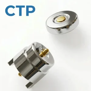
A magnetic pogo pin interface for a smart wearable is a material system rather than a single metal contact. Its performance depends on the plunger, barrel, spring, termination, mating target, plating layers, magnets, insulating housing, adhesives, potting materials and final enclosure. No individual material name, gold thickness, magnet grade or IP label can independently establish contact resistance, cycle life, corrosion resistance, skin compatibility or water resistance.
Smartwatches, fitness trackers, biometric rings, audio wearables and compact head-mounted devices may use exposed conductive contacts for charging, docking, detection or project-specific communication.Spring-loaded contacts can compensate for a controlled amount of dimensional variation, while magnets may assist the final approach or retention. However, the visible pogo pin tip is only one part of the complete interface.
Material selection must therefore begin with the complete mating system:
Wearable PCB → Contact Termination → Pogo Pin → Contact Interface →
Mating Target → Device PCB → Charging and Protection Circuit
The mechanical and environmental system also includes:
Magnets → Housing → Mechanical Stops → Adhesives or Potting →
Wearable Enclosure → Charging Accessory
Use the Correct Term: Magnetic Interface, Not a Magnetic Pogo Pin Material
A conventional pogo pin is not normally magnetic by itself. The magnetic function is usually provided by permanent magnets, ferromagnetic components or a magnetic return structure installed around the electrical contacts.| Interface Component | Primary Function | Typical Material Questions |
|---|---|---|
| Plunger | Moves against the mating target and forms the contact surface | Strength, conductivity, tip geometry, wear and plating adhesion |
| Barrel | Guides the plunger and contains the internal spring | Wall thickness, dimensional stability, internal finish and conductivity |
| Spring | Provides the force-versus-stroke response | Elastic range, fatigue behaviour, temperature and corrosion exposure |
| Termination | Connects the pogo pin to a PCB, FPC, wire or housing | Solderability, welding, mechanical support and thermal exposure |
| Mating target | Provides the opposing conductive surface | Base metal, finish, flatness, wear area and enclosure sealing |
| Permanent magnet | Assists capture, orientation or retention | Magnetization, coating, temperature, corrosion and surrounding components |
| Insulating housing | Positions and electrically separates contacts | Dimensional stability, moisture absorption, reflow temperature and chemical exposure |
| Adhesive or potting | Fixes, seals or mechanically supports the assembly | Adhesion, shrinkage, curing, flexibility, ageing and chemical resistance |
“Magnetic pogo pin connector” describes an assembled interface. It should not be interpreted as one universal material specification for the pogo pin itself.
Specify Every Pogo Pin Component Separately
A pogo pin is an assembly. The plunger, barrel, spring and termination may use different materials because each component performs a different mechanical and electrical function.Plunger Material Requirements
The plunger may need to provide:
- Mechanical strength at a small diameter
- Resistance to permanent bending
- A stable tip geometry
- A suitable conductive path
- Adhesion to the selected underlayer and finish
- Wear resistance against the target
- Compatibility with machining, forming and plating processes
A high-conductivity alloy is not automatically the best plunger material if it cannot maintain the required geometry or plating integrity.Barrel Material Requirements
The barrel may need to provide:
- Controlled internal diameter
- Stable wall thickness
- Plunger guidance
- Resistance to crimping or assembly deformation
- A suitable internal conductive path
- Compatibility with soldering, welding or insert molding
For a miniature contact, post-plating barrel dimensions and internal surface condition may be as important as the nominal raw material.Spring Material Requirements
The internal spring should be selected by:
- Required preload
- Required force at the nominal working stroke
- Maximum approved compression
- Spring diameter and available length
- Operating temperature
- Required fatigue life
- Environmental exposure
- Manufacturing and forming capability
No single spring alloy is mandatory for every wearable connector. The actual force curve and production consistency are more important than a general material label.Material Selection Must Begin with the Working Stroke
The spring force, wear, contact resistance and housing load all depend on the pogo pin compression.A simplified stroke calculation is:
S = Hfree - Hseatedwhere:
- S is the actual compression
- Hfree is the installed free height
- Hseated is the final distance from the pin mounting plane to the target
The project should calculate:
Smin = Hfree,min - Hseated,max

Snom = Hfree,nom - Hseated,nom

Smax = Hfree,max - Hseated,min
The required condition is:
Approved minimum stroke ≤ Smin ≤ Snom ≤ Smax ≤ Approved maximum stroke| Stroke Condition | Possible Material or Interface Effect |
|---|---|
| Insufficient compression | Low normal force, unstable contact and increased sensitivity to surface films |
| Nominal compression | Intended contact force, wear rate and electrical condition |
| Excessive compression | Spring overstress, housing load, barrel damage or target indentation |
| Unequal compression | Different wear and resistance between parallel contacts |
Material properties cannot compensate for an uncontrolled mechanical tolerance stack.The Plunger Tip and Target Form One Contact Pair
The pogo pin should not be evaluated without the mating target.The contact pair includes:
- Plunger-tip material
- Plunger-tip finish
- Target base material
- Target underlayer
- Target finish
- Surface roughness
- Normal force
- Contact area
- Sliding or wiping movement
- Environmental contamination
| Tip Geometry | Possible Benefit | Trade-Off |
|---|---|---|
| Rounded tip | General engagement with a flat or slightly curved target | May provide little wiping during purely axial compression |
| Flat tip | Distributes force over a larger local area | May become sensitive to target tilt and contamination films |
| Crowned or multi-point tip | Creates several local contact points | May increase target wear or retain debris |
| Intentional wiping geometry | Moves across a controlled target region | Adds friction, side load and plating wear |
A tip should not be described as automatically piercing sweat, oil or oxide. Representative contamination and wear tests are required.Plating Is a Layer System, Not a Gold-Thickness Number
Contact plating may include a substrate, one or more intermediate layers and a final mating finish.A complete plating specification should identify:
- Base material
- Surface preparation
- Activation process
- Underlayer material
- Underlayer thickness and tolerance
- Barrier layer where used
- Final contact finish
- Finish thickness and tolerance
- Hardness where relevant
- Porosity or defect acceptance
- Plated areas
- Masked areas
- Thickness-measurement method
- Finished dimensions after plating
Functions of the Underlayer
An underlayer may be selected to support:
- Adhesion between the substrate and final finish
- Diffusion control
- Surface levelling
- Corrosion-barrier performance
- Mechanical support for the final contact layer
The underlayer can become exposed after the final finish is worn or damaged, so its environmental behaviour matters.Functions of the Final Contact Finish
The final finish may influence:
- Oxidation behaviour
- Contact resistance
- Friction
- Wear
- Hardness
- Surface contamination
- Compatibility with the opposing target finish
A thicker final finish may provide more wear margin in some structures, but it does not independently supports cycle life, corrosion resistance or stable contact resistance.Do Not Copy One Plating Stack Across Every Wearable
A smartwatch, smart ring, TWS earbud and VR controller may experience different contact motion and contamination.| Application | Typical Exposure Question | Material-System Focus |
|---|---|---|
| Smartwatch | Perspiration, soap, skin oil and frequent wrist movement | Accessible targets, cleaning, sealing and body-contact boundary |
| Fitness band | Long wear periods, exercise sweat and flexible enclosure movement | Small target stability, corrosion and polymer compatibility |
| Smart ring | Hand washing, lotion, curved surfaces and size-specific charging docks | Target geometry, contamination access and miniature termination |
| TWS earbuds | Sweat, skin oil, earwax and deep charging cavities | Wet-contact control, cleaning access and case-side pogo pin wear |
| VR wearable | Perspiration, higher device mass and larger charging structures | Mechanical support, magnetic retention and thermal behaviour |
| Medical or wellness patch | Skin-contact duration, adhesives and disposable or reusable layers | Accessible materials, cleaning and complete device evaluation |
The correct plating and material system should be selected from the actual application rather than from a universal “wearable connector” formula.Galvanic Corrosion Is Only One Possible Failure Mechanism
Galvanic corrosion requires electrically connected dissimilar conductive materials in a corrosive electrolyte.

Wearable charging contacts may also experience:- General electrochemical corrosion
- Pitting at coating defects
- Crevice corrosion beneath residue
- Fretting corrosion caused by small movements
- Plating wear
- Salt-residue leakage
- Contamination-film formation
- Localized heating during charging
- Corrosion at exposed underlayers
A damaged contact should be inspected before assigning a corrosion mechanism.Evaluate Sweat as Part of a Mixed Contamination System
Real wearable exposure may include several substances at the same time.| Exposure | Possible Interface Effect | Required Project Definition |
|---|---|---|
| Perspiration | Electrolytic residue, corrosion and leakage between contacts | Wear time, exercise condition and exposure method |
| Skin oil | Surface films and dust retention | Contact location and cleaning frequency |
| Soap or detergent | Residue, material interaction and charging interruption | Expected user routine and drying instruction |
| Lotion or cosmetics | Film formation, polymer interaction and discoloration | Foreseeable products and exposure frequency |
| Dust and fibres | Blocked plunger movement or incomplete seating | Storage environment and connector orientation |
| Metallic particles | Bridging or collection around permanent magnets | Contact spacing, magnetic field and cleaning access |
| Cleaning agents | Coating, adhesive, housing or marking degradation | Approved chemical, method and number of cycles |
A salt-spray result alone cannot represent the combined effects of sweat, oil, voltage, movement and repeated user cleaning.Control the Electrical State of Wet or Exposed Contacts
Material selection is only one level of corrosion control. The charging circuit should also define when the source-side contacts are energized.Possible electrical states include:
- Continuously energized contacts
- Current-limited contacts
- Normally de-energized contacts
- Power enabled after device detection
- Power enabled after a valid voltage or identification check
- Power disabled after abnormal leakage is detected
- Power disabled after an overtemperature condition
Reducing the time during which wet or contaminated contacts carry voltage may reduce some electrochemical risks, but the complete control strategy must be validated.Contact Resistance Must Include the Complete Channel
The internal resistance of the pogo pin is only one part of the electrical path.A simplified model is:
    Rpath = RPCB1 + Rtermination1 + Rpogo + Rinterface +
    Rtarget + Rtermination2 + RPCB2
The voltage drop is:
Vdrop = I × RpathThe resistive power loss is:
Ploss = I² × Rpath

A contact-resistance claim should identify:- The tested part or complete channel
- The test current
- The working stroke
- The spring force
- The target material and finish
- The sample condition
- The environmental condition
- The measurement method
- The acceptance criteria
A generic “below 50 mΩ” value is not sufficient for engineering selection.Current Capacity Depends on the Complete Thermal System
A small contact may carry a project-defined current, but acceptable current cannot be determined from contact diameter alone.Current capability depends on:
- Plunger and barrel construction
- Internal spring and conductive path
- Working stroke
- Contact force
- Target material and finish
- PCB copper
- Number of parallel contacts
- Enclosure thermal conductivity
- Ambient temperature
- Charging duty cycle
- Permitted temperature rise
Parallel contacts may not share current equally when their compression, resistance or termination paths differ.| Parallel-Contact Difference | Possible Result |
|---|---|
| Different working strokes | Different force and interface resistance |
| Target tilt | One contact engages before the others |
| Different PCB routing | Unequal conductor resistance |
| Contamination on one target | More current may transfer through the remaining contact |
| Different termination quality | Local heating or channel imbalance |
Cycle Life Depends on the Complete Mating Pair
Mechanical endurance is affected by:- Pogo pin component materials
- Spring-force curve
- Working stroke
- Maximum compression
- Tip geometry
- Target finish
- Sliding or wiping distance
- Side load
- Electrical load
- Cycle speed
- Environmental exposure
- Cleaning intervals
- Failure and acceptance criteria
A plating thickness, spring alloy or material hardness should not be converted directly into a fixed number of cycles or years.

Mechanical operation without an electrical load and repeated mating under current are different test conditions.
Permanent Magnet Selection Requires More Than a Grade
A magnet designation does not define the complete magnetic behaviour of a wearable charging interface.The magnetic design should specify:
- Magnet material
- Dimensions and tolerances
- Magnetization direction
- Number and position of poles
- Surface coating
- Operating-temperature range
- Permitted irreversible demagnetization
- Adhesive or mechanical retention
- Magnetic return components
- Capture force
- Seated retention
- User-removal direction
- Nearby magnetic-sensitive components
Magnet Coating and Corrosion
Magnet coatings should be evaluated for:- Pinholes
- Edge coverage
- Chipping during assembly
- Adhesive compatibility
- Moisture exposure
- Salt and cleaning residue
- Wear against the surrounding housing
A high magnet grade does not establish corrosion resistance or adhesive reliability.Magnetic Force Is a System Result
The measured attraction depends on:- Magnet dimensions
- Air gap
- Target material
- Magnetization direction
- Alignment
- Housing thickness
- Return path
- Measurement direction
Capture force, seated retention and release force should be treated as separate requirements.Review Magnets Around Sensors, Speakers and Antennas
A wearable may contain:- Hall sensors
- Magnetometers or compass functions
- Speaker drivers
- Haptic components
- Wireless antennas
- Optical sensors
- Internal steel parts
- Additional permanent magnets
Alternating poles or magnetic return structures may reduce external field in a particular design, but they cannot ensure zero interaction.

The complete powered product should be evaluated using minimum and maximum production magnet conditions.
Housing Materials Control Position, Insulation and Assembly
The insulating housing may be required to maintain contact spacing and working stroke after molding, soldering, ageing and environmental exposure.Relevant housing properties include:
- Dimensional stability
- Molding shrinkage
- Moisture absorption
- Heat resistance
- Reflow compatibility where applicable
- Electrical insulation
- Creepage and clearance geometry
- Chemical compatibility
- Adhesion to metal inserts
- Resistance to cracking
- Colour and cosmetic stability
Material families such as LCP, PPS, polyamide or other engineering polymers may be evaluated, but no one polymer is universally correct.

The exact resin grade, fillers, molding direction and process conditions can influence the finished connector dimensions.
Insert Molding Does Not Automatically Create a Waterproof Interface
Insert molding can integrate metal contacts into a polymer component, but the final seal may still depend on:- Metal-surface preparation
- Insert geometry
- Polymer shrinkage
- Bond-line length
- Molding pressure and temperature
- Voids
- Thermal expansion
- Mechanical stress
- Post-molding assembly
The interface should be evaluated after thermal ageing, mechanical loading and environmental exposure.Adhesives and Potting Materials Need Their Own Specification
Adhesive or potting material may be used to fix magnets, seal contacts, support PCBs or close leakage paths.Define:
- Chemical family
- Viscosity
- Dispensing method
- Curing process
- Cure shrinkage
- Adhesion to every substrate
- Operating temperature
- Moisture uptake
- Hardness or flexibility
- Rework requirements
- Ageing and chemical resistance
- Permitted voids
A rigid potting compound may seal effectively but transfer stress into a PCB or contact insert. A softer material may reduce stress but allow movement or moisture diffusion.IP68 and 5ATM Describe Different Product Evaluations
IP classifications apply to the degree of protection provided by a defined enclosure.

Water-resistance markings for watches are evaluated under watch-specific requirements and test methods.| Claim | Primary Meaning | What It Does Not Automatically Prove |
|---|---|---|
| Connector IP rating | Defined protection of the tested connector or assembly | Complete wearable enclosure protection |
| Finished-device IP rating | Defined enclosure performance under the test condition | Sweat, soap, corrosion or safe wet charging |
| 5ATM watch marking | Watch water resistance under the applicable test and product definition | Connector-level IP68 or unlimited diving use |
| Static immersion result | Performance under the defined static test | All dynamic movement, impact or temperature-change conditions |
IP68 and 5ATM should not be combined into one universal connector statement.Water Resistance Does Not Establish Safe Wet Charging
A finished wearable enclosure may resist defined water exposure while its external charging contacts still need to be dry before charging.

Wet charging may introduce:- Leakage current
- Contact bridging
- Electrochemical corrosion
- Charging faults
- Localized heating
- Residue after evaporation
Product instructions, electrical protection and charging-state logic should address this separately from the enclosure rating.Skin-Contact Materials and Connector Materials Are Not Always the Same
The complete wearable should identify which connector materials are accessible during normal use.Review:
- Whether the target contacts touch the skin
- Whether the pogo pins are only inside the charger
- Contact duration and frequency
- Whether wear exposes an underlayer
- Whether corrosion products can migrate to the skin
- Whether cleaning residues remain on the product
- Whether adhesive or polymer surfaces are accessible
Terms such as “medical grade,” “hypoallergenic,” “pure gold” or “nickel-free” should not replace evaluation of the finished accessible material system.Miniaturization Changes the Material and Process Window
As contact dimensions decrease, several processes become more sensitive:- Machining burrs
- Plunger straightness
- Barrel-wall thickness
- Concentricity
- Spring insertion
- Plunger retention
- Plating-thickness variation
- Housing shrinkage
- Assembly coplanarity
- Inspection resolution
Plating thickness may become a meaningful part of the finished dimensional tolerance on a sub-millimeter component.

The drawing should distinguish:- Pre-plating dimensions
- Finished dimensions
- Critical geometric tolerances
- Measurement location
- Gauge capability
- Production inspection frequency
Do Not Publish ±0.01 mm Without a Defined Process
A tolerance statement should identify:- The controlled feature
- The datum system
- The measurement equipment
- Gauge resolution
- Measurement uncertainty
- Inspection temperature
- Sample size
- Production acceptance criteria
Machine resolution and product process capability are not the same.Material Selection Must Include Manufacturing Compatibility
| Process | Material Questions |
|---|---|
| Precision machining | Tool wear, burrs, straightness, surface condition and achievable wall thickness |
| Spring forming | Wire consistency, residual stress, force curve and fatigue |
| Electroplating | Coverage, thickness distribution, internal surfaces and post-plating dimensions |
| Insert molding | Metal adhesion, shrinkage, thermal expansion and leakage paths |
| SMT soldering | Coplanarity, thermal resistance, solderability and flux residue |
| Laser welding | Heat-affected zone, material compatibility, distortion and joint inspection |
| Adhesive bonding | Surface preparation, cure, bond-line control and ageing |
| Final assembly | Handling damage, magnet polarity, contact stroke and visual inspection |
Recommended Material-Selection Sequence
- Define the wearable application and charging architecture.
- Define whether pogo pins are located in the device, dock or cable.
- Complete the electrical Pin Map.
- Define voltage, current, temperature-rise and contact-resistance limits.
- Calculate minimum, nominal and maximum working stroke.
- Define the spring-force curve.
- Define tip geometry and target dimensions.
- Select plunger, barrel, spring and target materials separately.
- Develop the complete plating layer system.
- Define magnets, magnetic return structures and retention requirements.
- Select the housing, adhesive, potting and sealing processes.
- Review manufacturing, assembly and inspection capability.
- Build production-intent prototypes.
- Validate the complete wearable-and-charger interface.
Recommended Validation Plan
| Requirement | Possible Evaluation |
|---|---|
| Material identification | Confirm plunger, barrel, spring, target, magnet, housing and adhesive specifications |
| Plating construction | Layer material, thickness, distribution and finished dimensions |
| Working stroke | Minimum, nominal and maximum compression in the final product |
| Spring force | Force-versus-stroke curve on production-intent contacts |
| Target geometry | Dimensions, flatness, support, finish and credible wear area |
| Contact resistance | Defined test current, stroke, target and environmental condition |
| Voltage drop | Complete path at intended charging current |
| Temperature rise | Maximum intended charging condition and ambient temperature |
| Parallel-current sharing | Individual contact current and temperature where contacts are paralleled |
| Mechanical endurance | Project-defined cycles without electrical load |
| Powered endurance | Repeated mating or charging with the intended electrical load |
| Plating wear | Surface inspection before and after cycling |
| Fretting | Small-motion vibration and resistance variation |
| Perspiration exposure | Representative exposure followed by electrical and surface inspection |
| Mixed contamination | Sweat, oil, soap, lotion, dust and cleaning residue |
| Wet-contact response | Defined moisture condition and charging-control behaviour |
| Magnetic force | Capture, retention and removal in minimum and maximum production conditions |
| Magnet corrosion | Coating integrity, edges, adhesive joints and environmental exposure |
| Magnetic interaction | Sensors, speakers, antenna and complete device behaviour |
| Housing stability | Molding, reflow, thermal ageing and moisture exposure |
| Adhesive or potting | Bond strength, voids, shrinkage and environmental ageing |
| Enclosure protection | Complete finished wearable in the defined test condition |
| Cleaning | Approved user-cleaning method followed by functional verification |
| Production variation | Critical dimensions and assembled-interface capability |
Information Required for an Engineering Review
| Requirement Group | Information to Provide |
|---|---|
| Wearable type | Watch, band, ring, earbud, headset, patch or another device |
| Charging architecture | Dock, case, cable, puck or another structure |
| Contact location | Pogo pins in the device or charger and target location |
| Available space | Contact envelope, internal depth, pitch and restricted regions |
| Pin Map | Power, return, detection, identification, service or data |
| Electrical conditions | Voltage, continuous current, peak current and permitted voltage drop |
| Thermal requirement | Ambient temperature and permitted interface temperature rise |
| Working stroke | Minimum, nominal and maximum compression |
| Contact force | Required force at defined stroke positions |
| Mating motion | Axial, sliding, wiping, rotational or combined movement |
| Target contact | Material, dimensions, finish, flatness and support |
| Materials | Plunger, barrel, spring, termination and target requirements |
| Plating | Underlayers, final finish, thickness, plated areas and test method |
| Magnets | Size, grade, polarity, coating, force and restricted regions |
| Housing | Resin requirement, molding method, temperature and chemicals |
| Sealing | Insert molding, adhesive, potting, gasket or another process |
| Environment | Sweat, skin oil, soap, water, dust and cleaning conditions |
| Body contact | Accessible materials, contact duration and frequency |
| Durability | Charging frequency, cycle target, load and acceptance criteria |
| Files | 2D drawings, 3D models, PCB layout, schematic and charging-accessory model |
| Commercial | Prototype quantity, production forecast and development stage |
Common Engineering Mistakes
| Mistake | Possible Consequence | Better Approach |
|---|---|---|
| Calling the entire pogo pin one material | Plunger, barrel and spring requirements become unclear | Specify every component separately |
| Copying one plating stack into every wearable | The finish does not match the target, motion or environment | Select the layer system from the complete interface |
| Using gold thickness to supports cycle life | Force, stroke, target and contamination are ignored | Test the complete mating pair |
| Calling all sweat damage galvanic corrosion | The real failure mechanism remains unidentified | Inspect the material pair, residue, wear and electrical state |
| Assigning current from contact diameter | Voltage drop or temperature rise may be unacceptable | Test the complete electrical path |
| Claiming a universal 100,000-cycle life | The published value lacks test conditions | State the stroke, load, target, environment and criteria |
| Specifying a project-specified magnet grade without magnetic-system analysis | Excessive impact, sensor interaction or corrosion risk | Define the complete magnetic circuit and use case |
| Using magnet grade to define attraction force | Air gap, dimensions and target material are ignored | Measure the complete assembled system |
| Calling insert molding automatically waterproof | Interface shrinkage, voids and ageing remain untested | Validate the complete enclosure |
| Combining IP68 and 5ATM | Different test standards are presented as one claim | State each tested product and standard separately |
| Equating water resistance with safe wet charging | External charging contacts may still corrode or fault | Define the charging condition and drying requirements separately |
| Calling a plating biocompatible by itself | The final accessible materials and wear are not evaluated | Review the complete finished material system |
| Publishing ±0.01 mm without measurement details | The production capability cannot be verified | Define the feature, datum, gauge and capability method |
Engineering Reference Sources
Final standards, test conditions and acceptance criteria should be confirmed for the actual wearable product and target market.-
AMPP — Definition and conditions of galvanic corrosion
-
AMPP — Galvanic, fretting and other corrosion mechanisms
-
Samsung — Wearable cleaning, moisture and charging-surface guidance
-
IEC 60512-2-2 — Contact resistance using a specified test current
-
IEC 60512-2-1 — Contact resistance using the millivolt-level method
-
IEC 60512-9-1 — Mechanical operation endurance without electrical load
-
IEC 60512-9-3 — Mechanical operation with electrical load
-
IEC 60512-9-5 — Cyclic current-loading endurance
-
IEC 60512-13-1 — Engaging and separating force tests
-
IEC 60529 — Degrees of protection provided by enclosures
-
ISO 22810 — Water-resistant watches
Frequently Asked Questions
Are magnetic pogo pins made from one material?
No. The plunger, barrel, spring, termination and target may use different materials according to their mechanical, electrical and manufacturing functions.Does thicker gold plating supports longer connector life?
No. Life also depends on the substrate, underlayer, target finish, working stroke, force, mating motion, contamination and electrical load.Does gold plating prevent all sweat corrosion?
No. Corrosion performance depends on plating coverage, porosity, wear, exposed underlayers, the mating material, moisture and electrical state.Is all sweat-related damage galvanic corrosion?
No. Other mechanisms may include general electrochemical corrosion, pitting, crevice corrosion, fretting, plating wear and conductive residue.Does an a project-specified magnet configuration automatically provide better docking?
No. Docking depends on magnet dimensions, air gap, polarity, target material, housing geometry, spring force and user-removal direction.Can insert-molded contacts automatically achieve IP68?
No. Insert molding may form part of the sealing structure, but IP performance must be confirmed on a defined complete assembly.Are IP68 and 5ATM equivalent?
No. They are associated with different product definitions and test standards and should be reported separately.Can a water-resistant wearable be charged while wet?
Not automatically. Enclosure water resistance and wet external-contact charging are different conditions.Can contact diameter determine the charging current?
No. Current capability requires complete-path voltage-drop and temperature-rise evaluation.What information is required for a wearable connector material review?
Provide the wearable type, charging architecture, Pin Map, voltage, current, stroke, force, target, environmental exposure, sealing structure and available drawings.Prepare Your Smart Wearable Connector Project
Review

    individual pogo pin structures

when the project requires separately integrated spring-loaded contacts.

Review

    pogo pin connector assemblies

when several contacts should be positioned inside one insulating housing.

Review

    custom magnetic connector components

when the project requires coordinated pogo pins, targets, magnets and housings.

Review

    custom magnetic cable assemblies

when the required supply scope includes a finished charging cable, wire termination and strain relief.

Additional engineering resources are available through the

    CTP connector engineering guides
.

Submit the device model, charging-accessory design, Pin Map, electrical conditions, environmental requirements and available drawings through the

    Get Quote & Samples page
.


    CTP can review the connector supply scope, component materials, plating zones, pogo pin working stroke, target geometry, magnetic arrangement, housing structure and PCB, FPC or cable termination. Final material performance, corrosion resistance, cycle life, skin-contact suitability, enclosure protection, battery safety and finished-product compliance must be confirmed through approved drawings and project-specific validation.
CTP ENGINEERING PATHS
Choose the right path for your project
Move from application requirements to a connector pair, a data-capable cable assembly, or a charging cable configuration. Final specifications are confirmed against an approved drawing and project validation plan.
Magnetic Connectors
Connector geometry, pin layout, mechanical integration and OEM/ODM review.
Engineering overview → 02Magnetic Data Cables
Power and signal allocation, cable exit, interface selection and assembly review.
Cable engineering → 03Magnetic Charging Cables
Browse the complete cable catalog and shortlist a starting structure for customization.
View cable catalog →