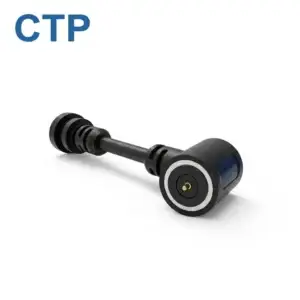
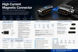
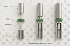
A magnetic pogo pin connector works by combining several separate
mechanical and electrical functions. Magnets assist capture and retention,
mechanical guides and datums establish the final mating position, and
spring-loaded pogo pins compress against mating targets to create the
electrical path. In more controlled systems, connection detection and power
sequencing can also distinguish magnetic attachment from a valid electrical
connection. Understanding these separate functions is the key to designing
a reliable magnetic interface.
What Is Inside a Magnetic Pogo Pin Connector?
A magnetic pogo pin connector is not a single component performing one
function.

It is normally an electromechanical assembly containing several functional
elements.| Element | Main Function |
|---|---|
| Permanent Magnets | Assist capture and provide part or all of the seated retention |
| Pogo Pins | Provide spring-loaded electrical contact and Z-axis compliance |
| Mating Targets | Provide the conductive landing surface for the pogo pins |
| Housing | Controls contact spacing and protects the assembly |
| Mechanical Guides | Control orientation and X-Y positioning |
| Mechanical Stops | Define final mating height and pogo pin compression |
| PCB / FPC / Cable | Connect the pogo interface to the rest of the electrical system |
These functions should remain conceptually separate.A useful model is:
    Magnetic System
    =
    Capture + Retention


    Mechanical System
    =
    Guidance + Datum + Final Stop


    Pogo Pin System
    =
    Spring Compliance + Electrical Contact


    Electronic System
    =
    Detection + Validation + Power / Signal Control

positioning and spring-loaded electrical contact in one removable
interface.
How Does a Magnetic Pogo Pin Connector Work Step by Step?
The complete operating principle becomes easier to understand when the
mating process is divided into individual states.
A typical sequence is:
    Approach
    →
    Magnetic Capture
    →
    Mechanical Guidance
    →
    Final Seating
    →
    Pogo Compression
    →
    Electrical Contact
    →
    Connection Validation
    →
    Power / Signal Operation


Not every connector uses all of these stages, but separating them reveals
which component is responsible for each function.
Stage 1: Magnetic Capture Begins During Approach
When the two connector halves move close enough to each other, the magnetic
field begins creating an attractive force.

This can help pull the mating assembly toward the intended connection
region.

This is the basis of the familiar “snap-to-connect” behavior found in many
magnetic charging and docking interfaces.
Capture Is Not the Same as Precision Alignment
A common misconception is that magnets automatically position every pogo
pin closely over its target.

In practice, magnetic attraction mainly helps the two connector halves find
each other.

Final precision positioning should normally come from mechanical features
such as:- guide walls;
- chamfers;
- locating bosses;
- asymmetric housings;
- mechanical datums;
- final stops.
A stronger design principle is:


    Magnet Finds the Interface
    →
    Mechanical Geometry Defines the Position
Magnet Polarity Can Help Control Orientation
Magnet arrangement can be designed so that some incorrect orientations are
less attractive or mechanically incompatible.

However, magnetic polarity should not be treated as the only protection
against electrical misconnection.

Multi-contact interfaces can also use:- asymmetric mechanical keying;
- different contact layouts;
- connection detection;
- module identification;
- controller-managed power enable.
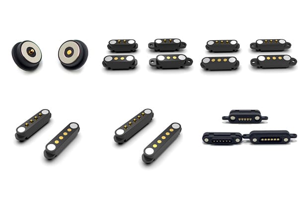
mechanical guides and contact arrangements while following the same
basic operating principle.
Stage 2: Mechanical Guidance Establishes Final Position
As the connector continues closing, the mechanical housing begins to take
over from the magnetic capture system.

This stage determines whether the pogo pins will land correctly on their
corresponding target pads.
Mechanical Geometry Controls X-Y Position
The allowed lateral tolerance depends on:- pogo tip diameter;
- target-pad dimensions;
- pin pitch;
- housing tolerances;
- PCB position;
- connector flatness;
- angular error.
Smaller target pads or tighter contact pitch can reduce the available
positioning margin.
The Final Z Position Should Be Mechanically Defined
The final distance between the two connector halves determines how far the
pogo pins are compressed.

That position should normally be defined by a mechanical stop or controlled
datum.

The design should not simply allow the magnets and pogo springs to find
their own equilibrium position.

A more controlled architecture is:


    Magnetic Capture
    →
    Mechanical Stop
    →
    Defined Pogo Compression
Stage 3: The Pogo Pin Compresses and Creates Contact Force
A pogo pin normally contains:- a plunger;
- a barrel;
- a spring;
- an electrical termination.
As the mating target pushes against the plunger, the spring compresses.

This creates normal force between the pogo tip and the target surface.
Working Stroke Is the Important Installed Parameter
A simplified relationship is:

S = Hfree - Hseated
where:
- S = actual installed compression;
- Hfree = installed free height;
- Hseated = final seated height.
The target is not simply to compress the pin as far as possible.

It is to keep the contact inside the approved working-stroke window across
the complete product tolerance stack.
Actual Stroke Depends on the Whole Assembly
Variation can come from:
- pogo free height;
- PCB thickness;
- solder height;
- housing tolerance;
- target height;
- assembly flatness;
- mechanical-stop variation.
Engineers should therefore calculate:


    Minimum Compression
    /
    Nominal Compression
    /
    Maximum Compression
Total Travel Is Not the Same as Recommended Working Stroke
The pogo pin may physically move beyond its intended operating range.

That does not mean the product should use all of that available travel.

Mechanical stops should protect the pogo pin from becoming the primary
structural load path.
Stage 4: Electrical Contact Is Created at the Pogo Tip and Target
Once the pogo pin reaches the correct compression, the tip presses against
the target and creates an electrical interface.

The quality of that interface depends on more than spring force alone.
Important variables can include:
- working stroke;
- contact force;
- pogo tip geometry;
- target-pad geometry;
- surface finish;
- cleanliness;
- alignment;
- electrical load;
- environmental exposure.
More Contact Force Is Not Automatically Better
Too little force can reduce contact margin.

Excessive force can increase:- spring reaction;
- target wear;
- housing load;
- magnetic retention requirements.
The appropriate contact force depends on the actual pogo pin geometry and
product requirement.
There Is No Universal Pogo Pin Force Range
Contact force should not be generalized into one value that applies to all
magnetic pogo pin connectors.

Different designs can require different:- spring rates;
- working strokes;
- pin diameters;
- contact forces;
- target structures.
The correct specification should come from the approved contact design and
mating condition.
Stage 5: The Complete Electrical Path Carries Power or Signals
Once the contact is established, current does not travel through the pogo
pin alone.
A simplified path can be:
    Source
    →
    PCB / Cable
    →
    Termination
    →
    Pogo Pin
    →
    Tip-to-Target Interface
    →
    Target
    →
    PCB / Cable
    →
    Load
A simplified resistance model is:
    Rpath =
    Rsource +
    Rtermination +
    Rpogo +
    Rinterface +
    Rtarget +
    Rload
Voltage drop follows:
Vdrop = I × Rpathwhile resistive loss follows:
Ploss = I² × RpathWhy Contact Resistance Alone Is Not Enough
Even if the pogo contact itself has a low resistance, the complete interface
can still experience additional loss from:- solder joints;
- PCB traces;
- small cable conductors;
- target surfaces;
- terminations.
Higher-current designs should therefore be validated using complete-path
voltage drop and temperature rise.
detection and selected signals, but each electrical function requires
its own validation.
How Do Multi-Pin Magnetic Pogo Connectors Work?
Multi-pin versions follow the same mechanical principle but allow different
contacts to carry different functions.
A Pin Map may include:
- power;
- power return;
- connection detection;
- module identification;
- control signals;
- selected data paths.
The engineering flow should be:


    System Functions
    →
    Pin Map
    →
    Required Contacts
    →
    Contact Layout
More Pins Do Not Automatically Mean More Current
Several contacts can be connected in parallel for power or return, but
equal current sharing should not be assumed.
Sharing can be influenced by:
- contact-resistance variation;
- working-stroke variation;
- target flatness;
- connector tilt;
- PCB routing;
- termination resistance.
More Pins Do Not Automatically Mean Higher Data Speed
Data capability depends on the complete electrical channel.Relevant parameters may include:
- signal-to-return arrangement;
- pin spacing;
- contact geometry;
- PCB launches;
- reference-plane continuity;
- FPC or cable construction;
- channel length.
A six-pin or eight-pin connector should therefore not automatically be
described as a high-speed data connector.
Stage 6: Magnetic Retention Keeps the Mating Halves Engaged
After the connector is seated, the magnetic system can help keep the two
halves together.

However, retention must work against several forces.
A simplified mechanical concept is:
    Available Magnetic Retention
    >
    Pogo Spring Reaction
    +
    Seal Reaction
    +
    Cable / Module Load
    +
    Expected Dynamic Separation Load


The actual design margin depends on the product.
Capture Force and Retention Force Are Not the Same Thing
Engineers should distinguish:| Mechanical Behavior | Meaning |
|---|---|
| Capture | How the connector behaves during approach |
| Seated Retention | How strongly the connector remains attached after seating |
| Axial Separation | Force required during straight pull-off |
| Peel Separation | Behavior when the connector is lifted from one edge |
| Off-Axis Load | Response to cable pull, rotation or side loading |
Stronger Magnets Are Not Automatically Better
Excessive magnetic attraction can increase:- removal effort;
- closing impact;
- housing stress;
- lateral sliding;
- ferromagnetic debris attraction.
Magnetic behavior should therefore be designed around the complete product
interaction.
Stage 7: The System May Need to Confirm That the Connector Is Valid
One of the most important concepts in magnetic connector engineering is:


    Magnetic Attachment
    ≠
    Mechanical Seating
    ≠
    Valid Electrical Connection


The connector may begin attracting before every pogo pin is correctly
compressed.
Possible intermediate states include:
- one edge contacting first;
- only some pogo pins engaged;
- foreign debris preventing complete seating;
- incorrect orientation;
- wet or contaminated contacts.
Connection Detection Can Be Added Where Required
Depending on the product, the Pin Map may include contacts for:- presence detection;
- module identification;
- pilot or make-first functions;
- controller-managed power enable.
A controlled system sequence can be:
    Approach
    →
    Capture
    →
    Seat
    →
    Detect
    →
    Identify
    →
    Validate
    →
    Main Power Enable


Not every magnetic connector requires this sequence.

It becomes useful where partial mating or exposed contacts create meaningful
electrical risk.
A Make-First Contact Does Not Suppress Arcing by Itself
A pilot contact can provide state information or help establish sequencing.

It does not automatically remove load current or suppress an electrical arc.

The system electronics must perform the required power-control function.
What Happens When a Magnetic Pogo Pin Connector Disconnects?
Separation is another designed operating state.

The connector may release through:- straight axial pull;
- edge peel;
- cable side load;
- intentional module removal.
As separation begins:


    Retention Force Falls
    →
    Pogo Compression Decreases
    →
    Contacts Separate
    →
    Electrical Path Opens
Breakaway Can Be a Product Feature
A magnetic interface can be designed to detach before a larger external
load is transferred into the product.

This can be useful in selected:- charging cables;
- portable devices;
- wearables;
- removable modules;
- docking systems.
But the required separation force must be designed for the actual
application.

A force suitable for a smartwatch charger may be inappropriate for an
industrial docking system.
How Materials Affect the Working Mechanism
Materials influence the electrical and mechanical behavior of the
connector, but there is no universal material stack that defines every
magnetic pogo pin connector.
Pogo Pin Materials Can Affect
- electrical conductivity;
- mechanical strength;
- wear behavior;
- spring behavior;
- manufacturability.
Surface Finish Can Affect
- initial contact resistance;
- wear;
- oxidation behavior;
- environmental durability.
However, one material or plating thickness should not be treated as a
universal specification for all magnetic connector applications.

The correct material system depends on:- working stroke;
- contact force;
- expected mating profile;
- electrical load;
- temperature;
- environment;
- target surface.
How Environmental Exposure Changes the Mechanism
Water, dust, sweat, oil or metallic debris can alter the mechanical and
electrical behavior of the connector.
For example:
    Ferromagnetic Debris
    →
    Magnetic Attraction
    →
    Incomplete Seating
    →
    Reduced Working Stroke
    →
    Unstable Contact
or:
    Surface Contamination
    →
    Contact Interface Change
    →
    Resistance Drift
    →
    Higher Voltage Drop / Heating


Environmental protection therefore needs to be evaluated as part of the
complete mating system.

A magnetic connector is not automatically waterproof because it has a flat
contact surface.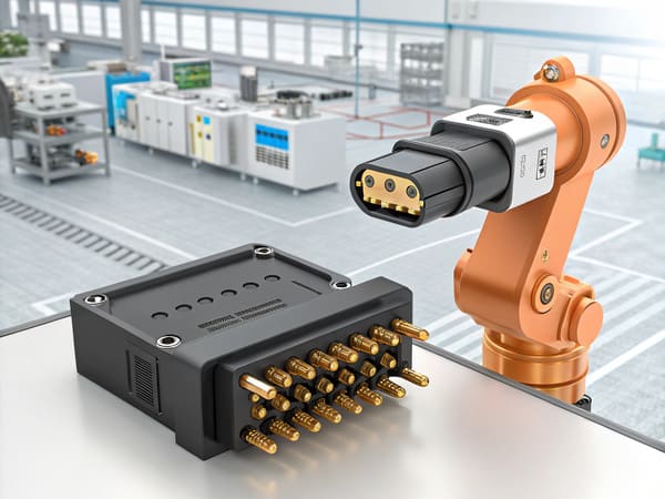
seating, electrical contact and connection validation.
The Complete Magnetic Pogo Pin Working Principle
| Stage | Main Component | Primary Function |
|---|---|---|
| 1. Approach | User / Robot / Product | Bring mating assemblies into the capture region |
| 2. Capture | Magnets | Assist final approach and retention |
| 3. Guidance | Mechanical Housing | Correct orientation and lateral position |
| 4. Final Seating | Mechanical Datum / Stop | Define final connector position |
| 5. Compression | Pogo Pin Spring | Create controlled normal contact force |
| 6. Electrical Contact | Pogo Tip + Target | Create the conductive interface |
| 7. Validation | System Electronics Where Required | Confirm valid connection before enabling functions |
| 8. Separation | Magnetic + Mechanical Interface | Release the connection under the intended removal condition |
Common Misunderstandings About How Magnetic Pogo Pins Work
| Common Assumption | Engineering Reality |
|---|---|
| Magnets closely align the connector | Magnets assist capture; mechanical datums should define final position |
| More magnetic force means better reliability | Retention must be balanced against removal force, spring reaction and product loads |
| Pogo pins absorb all mechanical misalignment | They mainly provide controlled compliance along the spring axis |
| Magnetic attachment means the circuit is valid | Partial mating can exist before complete electrical engagement |
| More pins mean more bandwidth | Signal performance depends on the complete channel architecture |
| Low pogo resistance proves high-current capability | The complete current path and temperature rise must be evaluated |
| Flat contacts mean waterproof | Ingress protection depends on the complete sealing boundary |
Where Does This Working Principle Create the Most Value?
Magnetic pogo pin interfaces are particularly worth evaluating when a
product benefits from:- frequent removable connection;
- blind or low-effort mating;
- automatic docking;
- controlled breakaway;
- compact external contact surfaces;
- custom combinations of power, detection and selected signals.
Possible product categories include:- wearable charging interfaces;
- portable electronics;
- removable medical-device modules;
- robot docking stations;
- industrial equipment;
- field-serviceable sensor modules.
Application suitability should still be determined from the actual
mechanical, electrical and environmental requirements.
When a Magnetic Pogo Pin Connector May Not Be the Best Architecture
Another connector architecture may be preferable when:- a strong positive mechanical lock is required;
- the interface is permanent;
- standardized third-party interoperability is essential;
- a standardized high-speed connector already satisfies the requirement;
- ferromagnetic contamination is difficult to manage;
- magnetic-sensitive components create unacceptable constraints;
- magnetic capture adds little value to the product.
Information Needed to Design a Magnetic Pogo Pin Connector
| Project Input | Information to Define |
|---|---|
| Interface Function | Charging, docking, module, service, test or another function |
| Available Space | X, Y and Z connector envelope |
| Mating Direction | Axial, side, angled or another approach |
| Mating Tolerance | X-Y-Z and angular variation |
| Working Stroke | Minimum, nominal and maximum compression |
| Pin Map | Power, return, detection, identification and signal functions |
| Electrical Load | Voltage, continuous current, peak current and duty cycle |
| Signal Requirement | Required control or communication channel |
| Magnetic Behavior | Capture, retention and separation requirements |
| Environment | Temperature, moisture, sweat, dust, salt, oil or chemicals |
| Lifecycle | Expected mating and service profile |
| Termination | PCB, FPC, wire or cable architecture |
Frequently Asked Questions
How do magnetic pogo pin connectors work?
Magnets assist capture and retention while mechanical guides establish the
final connector position. Spring-loaded pogo pins then compress against
mating targets to create the electrical contact.
What does the magnet do in a magnetic pogo pin connector?
The magnet primarily assists capture and retention. It does not replace the
pogo pin's electrical function or the mechanical datums that define final
alignment.
What does the pogo pin do?
The pogo pin provides a spring-loaded conductive contact and controlled
compliance along its spring axis.
Do magnets closely align pogo pins?
No. Magnets can guide the connector toward the mating region, while
mechanical guides, datums and stops should normally establish the final
position.
What is pogo pin working stroke?
Working stroke is the intended amount of spring-contact compression in the
final assembled interface. It should be checked across the complete product
tolerance stack.
Does stronger spring force create a better electrical connection?
Not automatically. Contact force must be balanced against wear, target
loading, spring reaction, magnetic retention and the specific contact
architecture.
What happens if a magnetic connector is only partially mated?
Some contacts may engage before others or before full working stroke is
reached. Where this matters, the system should treat partial mating as a
distinct electrical state.
Can magnetic pogo pin connectors carry high current?
They can be designed for higher-current applications, but capability depends
on the complete conductive path, working stroke, target, termination,
duty cycle and temperature-rise validation.
Can magnetic pogo pin connectors carry data?
Selected signal functions can be supported, but bandwidth depends on the
complete channel, including contact geometry, return paths, PCB transitions
and cable or FPC construction.
Are magnetic pogo pin connectors waterproof?
Not automatically. A magnetic interface can be integrated into a sealed
product, but ingress protection depends on the complete connector,
feedthrough, housing, seal and termination architecture.
Why can magnetic connectors break away?
The mating halves are retained by magnetic attraction rather than a
permanent mechanical lock in many designs. The actual breakaway behavior
depends on magnet layout, spring reaction, pull direction and product
geometry.
What is the difference between magnetic capture and electrical connection?
Magnetic capture means the connector has entered the magnetic engagement
region. A valid electrical connection normally requires final mechanical
seating and the intended pogo pin compression.
Request a Magnetic Pogo Pin Interface Engineering Review
Explore

    CTP custom magnetic connector solutions

for charging, docking and removable product interfaces.

Review

    pogo pin and spring-contact connector solutions

for different contact layouts and mounting structures.

Learn more about CTP engineering and manufacturing capabilities on the

    About Us page
. Submit your connector envelope, Pin Map, working stroke, voltage,
current, mating tolerance, capture and retention requirements,
environmental conditions and available 2D or 3D files to CTP for an
engineering review.
The interface can be reviewed as four separate engineering systems:
magnetic capture, mechanical positioning, spring-contact behavior and
electrical operation.
Final current capability, signal performance, magnetic behavior,
environmental protection and lifecycle should be confirmed against the
approved connector revision and project-specific validation conditions.
CTP ENGINEERING PATHS
Choose the right path for your project
Move from application requirements to a connector pair, a data-capable cable assembly, or a charging cable configuration. Final specifications are confirmed against an approved drawing and project validation plan.
Magnetic Connectors
Connector geometry, pin layout, mechanical integration and OEM/ODM review.
Engineering overview → 02Magnetic Data Cables
Power and signal allocation, cable exit, interface selection and assembly review.
Cable engineering → 03Magnetic Charging Cables
Browse the complete cable catalog and shortlist a starting structure for customization.
View cable catalog →