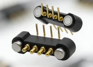
Your customer feels the connection before seeing the components behind it. A small accessory should settle comfortably into place. A removable module should meet its contacts without needing an awkward push. The spring force at the interface plays a part in that everyday experience.
A pogo pin force displacement curve shows how contact force changes as the plunger moves. It helps connect a small component choice with the way the finished product feels. Our range includes individual SMT contacts, bent-tail pins, integrated arrays and double-ended formats, giving you several ways to build the spring-contact interface around your device.
The spring brings useful movement to a small contact point
A rigid contact needs the two mating surfaces to arrive at a very specific relationship. A spring-loaded contact adds movement along the plunger axis, with contact pressure as it compresses. That makes it useful for products with separable parts and a defined seated position.
Our single SMT/SMD pogo pin, CTP-PP-1P-A01, puts that function into an individual board-mounted component. It suits a design that needs one contact point or a small number of points arranged around the available space.
For a compact accessory, that can keep the electrical connection discreet. The contacts can sit where they best meet the matching pads, while the housing guides the accessory into place. The visible product can remain simple even though the contact arrangement behind it is tailored to the device.
A single SMT contact leaves the layout in your hands
The individual format is valuable when the contact positions do not fit a regular block. You might have a housing post between two pads, or a contact location beside a board edge. Separate pins let the contact layout follow those features.
Spring force is selected with the complete mating arrangement in mind. A lightweight accessory and a firmly retained internal module may need different behavior. The useful advantage is having a contact format that can be considered as part of that product, rather than expecting every device to accept the same feel.
A pogo pin force displacement curve makes contact feel easier to discuss
The curve relates plunger movement to the force at that position. Free height, the intended working position and the permitted movement describe different parts of the connection. Understanding that relationship helps explain why a spring contact should be chosen for where it operates inside the product.
For a small dock, the amount of movement during seating matters as well as the final position. The user feels the whole approach. Looking at the force through that movement gives the designer a better basis for balancing comfortable handling with the required electrical contact pressure.
The curve for the selected part also keeps a comparison meaningful. A single force value without its compression position leaves too much unstated. A clear description of the working condition helps you compare suitable contact options without treating a catalog number as the complete product experience.
This is particularly useful in a handheld accessory that is attached several times during an ordinary day. The housing shape, guides and contact force all contribute to how easily the parts come together. The contact is small, but its choice can affect an interaction the user repeats often.
A bent tail makes room for a different board arrangement
The CTP right-angle pogo pin with a bent tail, CTP-PP-1P-RA-HC-A01, redirects the termination relative to the contact axis. It is worth considering when a straight termination does not suit the space behind the mating face.
The right-angle contact can suit a side-facing interface
A desk instrument might need its removable accessory to connect at the side, while the board lies along the bottom of the housing. A bent-tail format gives the designer another way to connect those two directions without changing where the user reaches the interface.
The spring-loaded plunger still works along its own axis. The bent tail changes the route into the device, rather than making the contact bend sideways. This separation is useful: the electrical termination can follow the board arrangement while the contact face follows the product’s mating direction.
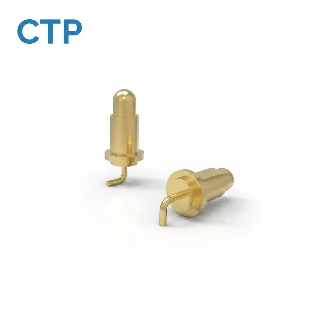
For the designer, that means more freedom to place the interface where it is convenient to use. The selected working movement and spring force can then be reviewed within that side-entry arrangement, with the enclosure providing the intended guidance and seated position.
Integrated arrays bring several spring contacts into one interface
When a device needs multiple electrical paths, our ten-contact SMT array, CTP-PC-10P-DR-A01, groups the positions in a five-by-two housing. The common body gives the contact pattern a defined outline on the PCB.
This can be convenient for a removable control module. Several assigned functions meet at one target area, and the connector can be arranged with the module’s guides and housing. The individual pins provide the spring action within that coordinated layout.
The number of spring contacts affects the complete mating action
With an array, the device engages several contacts during the same movement. The total reaction matters to the way it seats, especially when the accessory is light. Considering the array as a whole helps the design team balance the electrical paths with the intended handling.
A shorter eight-contact SMD array, CTP-PC-8P-DR-A01, offers a four-by-two alternative. If eight paths suit the circuit, that layout may be a more natural fit for the board and target area than a larger connector.
The advantage is choice within a consistent idea: several compliant electrical paths held in one housing. The contact count can follow the useful functions, while the shape and working position follow the product. More pins are helpful when the device needs them, rather than as an advantage on their own.
Two-sided contacts offer a different way to join removable parts
Our long-plunger double-ended contact, CTP-PP-1P-DE-A02, has electrical contact interfaces at both ends. One end has greater visible reach than the other, giving the designer another geometry to consider between facing surfaces.
For a module with a recessed contact area, that unequal shape may be useful. The contact can be evaluated with a carrier and two matching surfaces, rather than starting from a permanently wired connection. It remains one electrical path, with the movement at each end defined for the selected design.
The benefit here is the two-sided arrangement. It gives a removable assembly another way to meet the main device electrically. The internal construction and available travel should come from the part drawing, so the product design uses the contact for the operating condition it actually supports.
Balance contact pressure with the way your device connects
The relationship between the contact face and the internal connection can matter just as much as the spring itself. Our seven-contact magnetic FPC module, CTP-P3916, combines a multi-contact magnetic interface with an FPC connection. It offers a different route behind the mating face from a conventional wire bundle.
For a tightly packaged portable device, an FPC arrangement can be worth considering where the connection needs to follow the available internal space. The interface remains accessible at the outside of the device while the flexible circuit route connects it to the electronics. Its dimensions, routing and working contact condition are developed for the particular installation.
This is another way the range supports product design: you can consider the contact experience at the front and the connection space behind it together. A magnetic module, a PCB-mounted pin and a two-sided contact each place different demands on the housing. Choosing the appropriate structure gives the force discussion a real product context.
For a device that rests lightly in a cradle, the seated position and the way the cradle supports its weight deserve attention alongside spring force. For a module held by the enclosure, that support is already a different part of the design. The same nominal contact count can therefore lead to a different interface choice, depending on how the two product parts meet.
Our spring-contact formats let you compare more than one route to the same product goal. Individual SMT pins offer flexible positioning. Bent-tail contacts suit a different termination direction. Arrays group several paths together, while double-ended contacts bridge facing surfaces.
The guide to contact force in magnetic interfaces is useful when spring pressure also interacts with magnetic retention. The two forces contribute to different parts of the mating experience and should be considered with the housing and target arrangement.
For your product, start with the action you want the user to make. A gentle placement into a desk dock, a side-facing accessory and a retained internal module need not use the same contact shape. The force displacement curve helps refine that choice, while our range gives you practical formats to build it into the device.