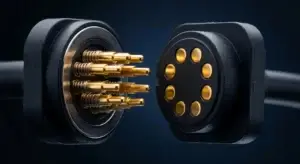
A 4-pin magnetic pogo connector provides four physical electrical contacts together with a magnet-assisted mating structure. It does not automatically define USB, fast charging or a fixed Pin Map. Engineers should first allocate the four contacts, then confirm the complete current path, signal requirements, pogo pin working stroke, magnetic capture and release behavior, PCB termination, exposed-contact safety and validation conditions.
A 4-pin magnetic pogo connector should be selected from the complete interface architecture rather than from Pin count alone.
Four contacts may be used for power and ground, power plus detection, power plus low-speed communication, parallel current paths or a project-specific combination.
In some projects, four contacts may be assigned to VBUS, ground and a differential data pair. However, having four physical pins does not by itself make the connector USB-compatible. The complete connector, PCB, cable, grounding and receiving circuit must be designed and validated for the required protocol.
This guide explains how to specify a
custom 4-pin magnetic connector
for PCB and device integration without applying universal assumptions about current, data rate, waterproofing, magnetic grade or mechanical life.What Is a 4-Pin Magnetic Pogo Connector?
A 4-pin magnetic pogo connector combines four conductive contacts with a magnetic capture or retention structure.A typical interface may include:
- Four spring-loaded pogo contacts
- Four corresponding mating pads or fixed contacts
- An insulating connector housing
- Magnets and a magnetic return structure
- Mechanical locating features
- A controlled working-stroke stop
- PCB, wire, cable or FPC termination
- Optional seals, overmolding or enclosure integration
The pogo pins generate contact pressure. The magnets assist the approach and may contribute to retention. The housing and mechanical stops should define the final mating position.| Interface Function | Primary Structure | Engineering Purpose |
|---|---|---|
| Electrical contact | Four pogo pins and mating targets | Carry the assigned power, ground, signal or detection functions |
| Initial capture | Magnetic field and housing geometry | Helps bring the two connector halves together |
| Final alignment | Locating walls, bosses, recesses or keys | Controls contact overlap and limits side loading |
| Working compression | Pogo pin stroke and mechanical stop | Keeps every contact inside its approved compression range |
| Retention | Magnets and device structure | Maintains the connected state under the defined load |
| Release | Axial pull, peel or project-specific motion | Defines how the connector disconnects |
Four Pins Do Not Define a Fixed Electrical Protocol
The term “4-pin” only describes the number of physical contacts. The function of each contact must be defined in the project Pin Map.Possible four-contact architectures include:
| Example Architecture | Possible Contact Allocation | Primary Engineering Review |
|---|---|---|
| Basic power with redundant paths | Two positive contacts and two return contacts | Current sharing, sequencing and exposed-contact safety |
| Power plus detection | Power, ground, detection and identification | Contact sequence and device recognition logic |
| Power plus communication | Power, ground and two signal contacts | Signal return path, routing and channel validation |
| Sensor interface | Power, ground and two sensor or control functions | Noise, reference ground and signal conditioning |
| Project-specific interface | Four customer-defined electrical functions | Voltage, current, spacing and mating-state analysis |
These are architecture examples only. They are not a fixed wiring definition for every 4-pin magnetic connector.Can a 4-Pin Magnetic Connector Support USB?
Four contacts can be allocated to a USB-style power and differential-data architecture, but Pin count alone does not establish USB compliance or reliable data performance.A USB-oriented design would need to define:
- Power and ground contacts
- The two differential data contacts
- Contact order and physical arrangement
- Signal-return path
- PCB routing from the controller to the connector
- Cable construction on the mating side
- Connector transition and discontinuity
- Crosstalk between power and signal contacts
- Performance in fully mated and partially mated states
The complete source-to-receiver channel should be evaluated. A four-contact connector with continuity on all four pins may still fail to meet the required signal-performance margin.Do not publish “USB 2.0 compatible,” a fixed data rate or “high-speed data” based only on the presence of four contacts. Protocol claims should be supported by complete channel-level validation.
Step 1: Define the Four-Contact Pin Map
The Pin Map should be approved before the PCB footprint, magnet arrangement and connector housing are frozen.Pin Map Planning Table
| Contact | Project Function | Required Review |
|---|---|---|
| Pin 1 | Defined by the customer schematic | Voltage, current and state before full mating |
| Pin 2 | Defined by the customer schematic | Ground or signal-return requirement |
| Pin 3 | Power, signal, detection or sensing | Spacing, routing and contact sequence |
| Pin 4 | Project-specific function | Identification, communication or redundant path |
For each contact, define:
- Electrical function
- Operating voltage
- Continuous current
- Peak current and duration
- Signal type
- Whether the contact is energized when exposed
- Required mating sequence
- Short-circuit and reverse-polarity protection
Step 2: Choose the Contact Layout
Four contacts may be arranged in a straight line, square pattern, circular pattern, staggered pattern or another project-specific geometry.| Layout | Possible Benefit | Primary Concern |
|---|---|---|
| Single row | Simple PCB routing and easy contact identification | Longer connector length |
| Two-by-two layout | Compact length and width balance | Orientation and diagonal offset conditions |
| Circular layout | Suitable for round enclosures or central interfaces | Rotational orientation and Pin Map control |
| Staggered layout | Supports contact sequencing or custom space constraints | Target-pad design and inspection complexity |
| Asymmetric layout | May help prevent incorrect orientation | Dedicated tooling and device-specific integration |
The layout should be selected together with the mating targets, PCB routing and magnet arrangement. Do not add the target pads only after the connector housing is complete.Step 3: Select the Pin Pitch and Contact Spacing
Pin pitch is the center-to-center distance between adjacent contacts. There is no universal pitch that is correct for every 4-pin magnetic connector.Pitch selection should consider:
- Pogo pin outside diameter
- Mating-pad dimensions
- Voltage and insulation requirements
- PCB routing capability
- Housing wall thickness
- Molding and assembly tolerance
- Magnet position
- Contamination and environmental exposure
- Offset and partial-mating conditions
A smaller pitch can reduce the connector footprint, but it can also reduce mechanical, electrical and manufacturing margin.Step 4: Define the Complete Current Path
The connector current capability depends on the complete path rather than the number or diameter of the pogo pins alone.The complete path may include:
- Power source
- PCB trace or cable conductor
- Connector termination
- Pogo pin internal current path
- Plunger-to-target interface
- Mating pad or fixed contact
- Receiving PCB or cable
- Electrical load
Specify:
- Continuous current
- Peak current
- Peak duration
- Duty cycle
- Ambient temperature
- Maximum permitted voltage drop
- Maximum permitted temperature rise
- Working stroke during the power test
- Wire gauge and PCB copper structure
“Supports 3A,” “supports 5A” or another current value is incomplete unless the contact construction, working stroke, conductor size, test assembly and thermal limit are defined.Contact Resistance Requires a Test Boundary
A resistance result should state whether it includes:
- The internal pogo pin only
- The pogo pin and mating target
- The PCB or cable termination
- PCB traces and vias
- Wire and cable conductors
Also define:
- Measurement points
- Test current
- Working stroke
- Sample temperature
- Initial or post-conditioning state
Resistance results should only be compared when the measurement boundaries and test conditions are equivalent.Parallel Contacts Do Not Automatically Share Current Equally
Two contacts may be connected in parallel for positive power and two for return, but current distribution may differ between the parallel paths.Current sharing can be affected by:
- Working-stroke variation
- Spring-force variation
- Contact-resistance variation
- Mating-pad alignment
- Unequal PCB routing
- Wire and solder-joint variation
Where parallel paths carry meaningful current, evaluate individual path voltage drop and temperature where practical.Step 5: Define the Pogo Pin Working Stroke
The working stroke is the amount each pogo pin is compressed after the connector reaches its final seated position.The dimensional stack may include:
- Pogo pin free height
- Connector installed height
- PCB thickness and position
- Housing dimensions
- Mating-target height
- Mechanical-stop position
- Adhesive, seal or overmolding thickness
- Enclosure deformation
| Assembly Condition | Possible Risk | Required Verification |
|---|---|---|
| Minimum compression | Insufficient force or intermittent contact | Minimum force and electrical stability |
| Nominal compression | Primary operating condition | Resistance, voltage drop and mechanical load |
| Maximum compression | Excessive force, PCB deflection or over-travel | Maximum force and remaining travel margin |
| Uneven compression | Different contacts may have different force or resistance | Housing flatness and pin-by-pin comparison |
The mechanical stop should control the final position. The magnets should not be allowed to drive the pogo pins into uncontrolled full travel.Step 6: Calculate the Total Spring Reaction
Four pogo pins generate a combined mechanical reaction when compressed.The total connector load depends on:
- Force per pogo pin
- Working stroke
- Number of contacts compressed
- Force tolerance between contacts
- Housing and PCB stiffness
Excessive total force may increase connector impact, PCB bending, housing deformation or the magnetic force required to maintain mating.

Insufficient force may reduce contact stability, especially at the minimum-compression tolerance condition.
Step 7: Engineer Magnetic Capture, Retention and Release Separately
Magnetic behavior should not be defined by magnet grade alone.The complete magnetic system may be affected by:
- Magnet material
- Magnet dimensions
- Number and arrangement of magnets
- Air gap
- Steel return components
- Housing thickness
- Connector face geometry
- Pogo pin spring reaction
- Pull direction
- Cable exit direction
Define at least three different behaviors:
| Magnetic Behavior | Engineering Meaning |
|---|---|
| Capture behavior | How the connector responds when the two halves first approach |
| Retention behavior | How the connector remains mated under the defined axial, lateral or cable load |
| Release behavior | How the connector separates under axial pull, peel or another direction |
A stronger magnet is not automatically better. Excessive magnetic force may increase mating impact, removal force, enclosure loading and pogo pin compression.a project-specified magnet grade is one possible magnet grade, not a universal requirement. Final selection should be based on the complete magnetic circuit, operating temperature, dimensions and required capture and release behavior.
Step 8: Review Every Mating State
A magnetic connector does not move directly from completely disconnected to closely mated. It may pass through offset, rotated and partial-contact positions.Review these states:
- Completely disconnected
- Approaching but not touching
- Offset contact
- Rotated contact
- One-contact-first condition
- Partial compression
- Fully seated
- Separation under load
For each state, evaluate:
- Which electrical contacts are touching
- Whether exposed contacts are energized
- Whether power can bridge adjacent contacts
- Whether reverse polarity is possible
- Whether the data or detection contacts connect first
- Whether the magnets can hold an unsafe partial position
- Whether a mechanical key is required
Magnetic polarity alone should not be treated as the only short-circuit prevention method. The connector geometry, Pin Map and electronic protection should be reviewed together.Step 9: Select the PCB or Cable Termination
| Termination | Possible Application | Primary Engineering Review |
|---|---|---|
| SMT | Low-profile PCB-mounted connector | Footprint, paste, reflow, coplanarity and mechanical support |
| Through-hole / DIP | Connector using extended PCB solder tails | Finished holes, soldering process and installed height |
| Wire or solder cup | Cable-side connector or internal harness | Wire gauge, soldering, Pin Map and strain relief |
| FPC | Thin devices or connector separated from the main PCB | Reinforcement, bend radius and termination stability |
| Integrated module | Connector supplied with PCB, cable, housing or seals | Complete dimensional, electrical and production validation |
Browse

    4-pin magnetic cable connector assemblies

when the project requires a completed cable-side interface rather than only a PCB-mounted connector.
SMT, Through-Hole and Right-Angle Are Not Simple Quality Levels
SMT is not automatically only for consumer products, and through-hole is not automatically mechanically superior in every device.The correct structure depends on:
- Available PCB area
- Connector height
- Production process
- Expected mechanical load
- Housing support
- Inspection access
- Repair and service strategy
The solder joint should not be expected to absorb all connector impact, cable pull or user-applied side loading. Housing support and a defined load path are required.Step 10: Design the Mating Target
Each pogo pin requires a corresponding conductive target pad or fixed contact.The mating side should define:
- Pad dimensions
- Pad pitch and position
- Surface finish
- Flatness
- Mechanical support
- Wear area
- Minimum contact overlap
- Spacing to adjacent electrical functions
A larger target pad can improve positional tolerance, but it may also increase the risk of one pogo pin touching the wrong electrical area during offset mating.Step 11: Separate Plating Requirements from Waterproofing
Contact plating can support conductivity, wear resistance and environmental stability, but it does not independently create a waterproof connector.A plating specification should identify:
- Plunger base material
- Barrel or target base material
- Underplate
- Final contact finish
- Finish thickness or approved range
- Which surfaces receive the finish
- Expected mating and environmental conditions
Requirements such as nickel-free construction, skin-contact compatibility or medical-device suitability must be evaluated against the actual material stack and applicable product requirements. They should not be assumed for every wearable or medical connector.Step 12: Define Waterproofing at the Complete Assembly Level
A pogo pin, magnet or gold-plated contact does not independently carry an IP rating.Ingress protection may depend on:
- Pin-to-housing interfaces
- Housing joints
- PCB, FPC or wire entry
- Gaskets and O-rings
- Adhesive or potting
- Cable overmolding
- Device enclosure
- Mated and unmated conditions
If an immersion requirement exists, the test depth, duration, connector state and complete tested assembly must be defined in the project validation plan.

Do not publish IPX8, IP68 or another rating until it is tied to an actual tested configuration.
4-Pin Magnetic Connector Selection Matrix
| Project Requirement | Recommended Starting Direction | Primary Review |
|---|---|---|
| Power only with higher path redundancy | Parallel positive and return contacts | Current sharing and exposed-contact safety |
| Power plus device detection | Power, ground, detection and identification Pin Map | Contact sequencing and electronic logic |
| Power plus low-speed communication | Power, ground and two signal contacts | Return path, noise and channel validation |
| USB-oriented interface | Power, ground and differential-data pair | Complete connector, PCB and cable channel |
| Thin device PCB integration | Low-profile SMT connector | Reflow, coplanarity and enclosure support |
| Connector separated from main PCB | FPC, wire or integrated module | Strain relief and conductor routing |
| User-detachable charging cable | Magnetic cable connector assembly | Release behavior, cable load and exposed contacts |
| Environmentally sealed device | Integrated connector and enclosure sealing design | Complete mated and unmated validation |
Recommended Engineering Validation
| Requirement | Recommended Evaluation |
|---|---|
| Dimensions | Connector, PCB, target pad, installed height and enclosure inspection |
| Pin Map | Continuity, polarity and short-circuit verification |
| Working stroke | Minimum, nominal and maximum compression conditions |
| Spring force | Individual-contact and total connector-force measurement |
| Magnetic behavior | Capture, retention and release testing in defined directions |
| Mating states | Offset, rotated, partial, fully seated and separation conditions |
| Contact resistance | Defined channel-level measurement at the approved working stroke |
| Power operation | Voltage-drop, current-sharing and temperature-rise testing |
| Signal operation | Application-specific complete-channel evaluation |
| Mechanical operation | Project-defined mating-cycle test with post-test inspection |
| Environmental exposure | Application-specific temperature, humidity, contamination or chemical testing |
| Ingress protection | Complete connector and enclosure test in the defined state |
| Production process | Production-intent PCB, cable, overmolding and assembly trial |
Information Required for a Custom 4-Pin Connector
- Application and device type
- Complete four-contact Pin Map
- Operating voltage
- Continuous and peak current
- Signal type and required data rate
- Available connector dimensions
- Preferred contact layout
- Required pin pitch
- Working height and compression range
- Required spring force
- PCB, wire, cable or FPC termination
- Mating-target dimensions and finish
- Capture, retention and release requirements
- Mating direction and cable exit direction
- Enclosure and PCB drawings
- Expected mating frequency
- Operating environment
- Prototype and annual production quantity
Common Selection Mistakes
| Mistake | Possible Consequence | Better Approach |
|---|---|---|
| Assuming four pins automatically mean USB | The complete channel may not support the protocol | Define and validate the full electrical path |
| Selecting only by magnet grade | Incorrect capture, release or temperature behavior | Design the complete magnetic circuit |
| Using magnets as the final alignment stop | Excessive impact or pogo pin compression | Use housing guidance and a mechanical stop |
| Ignoring partial mating | Short circuit, reverse contact or unstable power | Review every credible mating state |
| Using one current value without conditions | Unexpected voltage drop or temperature rise | Define the complete current path and thermal limit |
| Assuming parallel pins share current equally | One path may carry excessive current | Use symmetric routing and path-level testing |
| Calling a plated contact IPX8 | The enclosure performance is misrepresented | Test the complete sealed assembly |
| Relying on pogo pins for alignment | Side loading, wear or sticking | Add mechanical guides and locating features |
| Freezing the PCB before the Pin Map | Late rerouting and enclosure redesign | Approve the electrical architecture first |
Frequently Asked Questions
Does a 4-pin magnetic pogo connector automatically support USB?
No. Four contacts can be assigned to a USB-style power and data architecture, but protocol support depends on the complete connector, PCB routing, cable, return path and receiving circuit.Can all four contacts be used for power?
Yes, selected projects may use parallel positive and return contacts. Current sharing and thermal performance must still be evaluated across the complete paths.Can a 4-pin connector carry power and signals at the same time?
Yes. The contacts may be allocated to power, ground and selected signal functions according to the approved Pin Map.Is a project-specified magnet grade required for a magnetic connector?
No. Magnet selection depends on dimensions, air gap, magnetic circuit, operating temperature and required capture and release behavior.How should magnetic holding force be specified?
Define the test direction, connector state, cable load and required capture, retention and release behavior rather than using one isolated force value.Can the connector use SMT or through-hole mounting?
Both structures can be evaluated. The correct option depends on PCB space, assembly process, installed height and mechanical support.Can this connector be waterproof?
Environmental sealing can be developed, but the rating belongs to the complete connector and device assembly under a defined test condition.Does gold plating determine salt-spray performance?
Not by itself. Environmental performance depends on the complete plating stack, base materials, exposure state, connector construction and acceptance criteria.How much current can a 4-pin magnetic connector carry?
Current capability is project-specific and depends on the contact construction, Pin Map, parallel paths, working stroke, PCB or cable conductors and permitted temperature rise.What files should be submitted for customization?
Provide the four-contact Pin Map, PCB and enclosure drawings, electrical requirements, working height, magnetic-force requirements, cable structure and expected quantity.Prepare Your 4-Pin Magnetic Connector Project
Browse

    4-pin magnetic connector designs
,
compare the complete

    custom magnetic connector range
,
review

    4-pin magnetic cable connector assemblies
,
or access the

    connector engineering guides
.

Submit your Pin Map, PCB, cable and enclosure drawings through the

    Get Quote & Samples page
.

CTP can review the four-contact Pin Map, contact layout, current path, signal requirements, pogo pin working stroke, magnetic arrangement, PCB or cable termination and enclosure integration before prototype development. Final specifications should be confirmed in the approved project drawing and validation plan.CTP ENGINEERING PATHS
Choose the right path for your project
Move from application requirements to a connector pair, a data-capable cable assembly, or a charging cable configuration. Final specifications are confirmed against an approved drawing and project validation plan.
Magnetic Connectors
Connector geometry, pin layout, mechanical integration and OEM/ODM review.
Engineering overview → 02Magnetic Data Cables
Power and signal allocation, cable exit, interface selection and assembly review.
Cable engineering → 03Magnetic Charging Cables
Browse the complete cable catalog and shortlist a starting structure for customization.
View cable catalog →