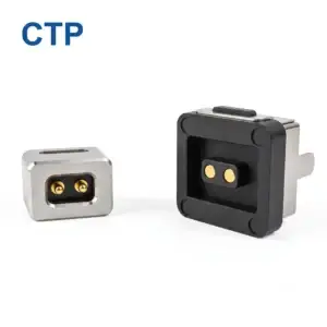
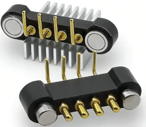
A custom OEM magnetic pogo pin connector can give a device a compact charging interface, controlled breakaway behavior, blind docking and a connector structure designed around the enclosure. However, the same level of customization that creates product differentiation can also introduce sourcing bottlenecks.
Projects are often delayed not because pogo pins or magnets are unavailable, but because the design depends on too many unique materials, unclear tolerances, single-purpose tooling or specifications that continue changing after prototype approval.
The most reliable sourcing strategy is therefore not to customize every component. It is to identify which parts of the connector create real value for the finished product, reuse stable platforms where possible and control the remaining custom elements through drawings, tooling, forecasts and change-management procedures.
The best OEM connector is not always the most customized connector. It is the design that meets the device requirements while maintaining a practical manufacturing, inspection and supply path.
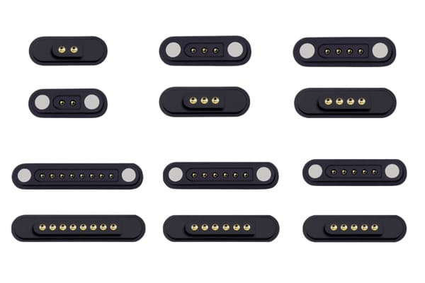
What Does “Custom OEM Magnetic Pogo Pin Connector” Mean?
In an OEM project, the connector is developed for integration into the customer’s device or equipment. The final structure may be manufactured according to the customer’s drawing, a jointly developed specification or a supplier platform modified for the application.
Customization may involve:
- pin count and pin assignment;
- connector shape and dimensions;
- pogo pin diameter, height and working stroke;
- spring-force range;
- magnet dimensions, position and polarity;
- mating-pad geometry;
- PCB, FPC, wire or cable termination;
- housing material and color;
- overmolding and strain relief;
- mechanical guidance and anti-mismating features;
- sealing and environmental protection;
- marking, packaging and labeling.
Not every project needs all of these elements to be redesigned. The first sourcing decision should be determining the correct level of customization.
Three Levels of OEM Connector Customization
| Customization level | Typical scope | Sourcing impact |
|---|---|---|
| Standard platform | Existing connector with changes to cable length, color, pin map, label or packaging. | Lower tooling risk and easier material planning. |
| Semi-custom platform | Existing pogo pins, magnets or termination structure combined with a new housing or contact layout. | Balanced development effort with moderate tooling and qualification requirements. |
| Full custom design | New pogo pin, magnet layout, housing, tooling, cable head and production process. | Greater design freedom but more dependence on tooling, custom materials and validation. |
A full custom design is justified when existing platforms cannot meet critical size, current, retention, pin-layout or environmental requirements. It should not be selected only because the product team wants every component to look unique.
Where Sourcing Bottlenecks Usually Begin
Connector supply problems often originate during product definition, long before the first purchase order is placed.
Typical bottlenecks include:
- requirements changing after tooling begins;
- one unique material being specified without an approved alternative;
- custom magnet sizes with high minimum order quantities;
- plastic housings that require several mold revisions;
- special plating requirements without clear thickness criteria;
- nonstandard wire colors or cable jackets;
- tooling owned or controlled by an unidentified sub-supplier;
- production forecasts that vary significantly from the original quotation;
- critical dimensions that cannot be measured efficiently during production;
- design changes communicated through email without updating the drawing.
These issues are easier to prevent during design review than to correct after production materials have been purchased.
1. Customize the Product Interface, Not Every Internal Component
Customers often need a unique external connector shape because the interface affects enclosure appearance, user interaction and device integration. That does not mean the internal contact system must also be completely new.
Where technically suitable, an OEM design may reuse:
- an existing pogo pin diameter and structure;
- a known spring-force range;
- a standard magnet size;
- a common wire gauge;
- an existing cable construction;
- a proven plating specification;
- a standard PCB or FPC termination;
- an existing production test method.
The custom value can then be concentrated in:
- housing geometry;
- pin arrangement;
- magnet location;
- mating direction;
- enclosure mounting;
- cable-head appearance;
- customer-specific pin assignment.
This modular approach can reduce dependence on unique raw materials and simplify later production scaling.
2. Freeze the Device Interface Before Freezing the Internal Design
The customer and supplier should first agree on the interface between the connector and the finished device.
The interface definition should normally include:
- maximum connector envelope;
- mounting position;
- mating direction;
- mating-pad location;
- acceptable misalignment;
- required working compression;
- cable or FPC exit direction;
- retention or breakaway-force range;
- enclosure reference surfaces;
- customer PCB keep-out area.
Once these boundaries are stable, the supplier has more flexibility to select internal components that are manufacturable and available.
The customer controls the functional interface and critical performance requirements. The supplier should retain reasonable flexibility in noncritical internal details, provided that changes remain within the approved specification.
3. Identify Long-Lead Components During Feasibility Review
Not every component in a magnetic pogo pin connector has the same procurement cycle.
Potential long-lead or minimum-order items may include:
- custom magnets;
- special copper alloys;
- nonstandard plating systems;
- custom plastic resin colors;
- flame-retardant or medical-use plastics;
- special cable jackets;
- low-volume custom FPCs;
- custom overmolding tools;
- precision stamping or machining tools;
- customer-specific packaging trays.
The quotation should therefore separate:
- prototype material availability;
- tooling lead time;
- first production material lead time;
- repeat-order production lead time;
- minimum order quantity;
- minimum material-purchase quantity;
- material shelf-life limitations.
A prototype may use materials already available in small quantities, while mass production requires a new minimum purchase. Procurement teams should not assume that prototype availability represents production availability.
4. Use a Component Risk Classification
A simple component-risk review helps both sides understand where supply interruptions are most likely to occur.
| Risk level | Typical component | Recommended action |
|---|---|---|
| Low | Common wire, standard packaging or existing pogo pin platform. | Confirm normal lead time and approved specification. |
| Medium | Custom housing, dedicated PCB, special cable length or nonstandard magnet arrangement. | Define tooling ownership, buffer stock and change-control requirements. |
| High | Unique material, single-source sub-supplier, custom plating or unusual resin. | Evaluate alternatives, minimum purchase, safety stock and requalification plan. |
The risk classification should be reviewed whenever the design, volume forecast or production site changes.
5. Clarify Tooling Ownership and Maintenance
Custom connectors may require several types of tooling:
- plastic injection molds;
- insert-molding tools;
- overmolding molds;
- pogo pin machining fixtures;
- assembly jigs;
- magnet-polarity fixtures;
- electrical test fixtures;
- packaging trays.
Before paying tooling charges, the customer should understand:
- who owns the tooling;
- where it will be stored;
- which supplier or sub-supplier operates it;
- expected tooling life;
- maintenance responsibilities;
- what happens if the tool is damaged;
- whether replacement inserts are available;
- whether the tooling can be transferred;
- how tooling revisions are approved;
- whether the tooling cost includes test fixtures.
A mold existing in a supplier network does not automatically mean the customer can move it to another facility. Ownership and transfer rights should be documented.
6. Design Production Tests at the Same Time as the Connector
A connector may be easy to prototype but difficult to inspect efficiently in production.
Critical characteristics may include:
- pogo pin installed height;
- working stroke;
- spring force;
- pin pitch;
- magnet polarity;
- magnetic retention force;
- continuity;
- pin assignment;
- contact resistance;
- cable length;
- housing dimensions;
- appearance and assembly position.
Each critical characteristic should have:
- a defined specification;
- a practical measurement method;
- suitable equipment or fixture;
- inspection frequency;
- acceptance criteria;
- a reaction plan for nonconforming results.
If a dimension cannot be measured reliably after final assembly, the supplier may need an in-process control or a dedicated fixture.
7. Separate Prototype MOQ from Production MOQ
Prototype quantities are normally produced through flexible, labor-intensive methods. Production quantities are based on material purchases, tooling capacity, machine setup and packaging efficiency.
These are different commercial conditions.
Prototype quantity may be influenced by:
- available sample components;
- manual assembly time;
- temporary tooling;
- engineering inspection requirements;
- the number of design variants being evaluated.
Production MOQ may be influenced by:
- minimum magnet purchase;
- plating-lot requirements;
- custom wire or cable purchase;
- molding setup;
- machine setup;
- packaging-lot quantity;
- production-line efficiency.
Procurement teams should ask for both values separately instead of assuming the sample quantity can become the repeat-order MOQ.
8. Provide Forecasts That Match the Actual Ramp Plan
A supplier cannot plan materials and production capacity from an annual volume alone. The timing of that volume matters.
A useful forecast should show:
- engineering sample quantity;
- customer validation quantity;
- pilot-build quantity;
- first mass-production order;
- monthly ramp forecast;
- expected peak volume;
- program lifetime;
- possible seasonal variation.
For example, an annual forecast of 120,000 units could mean:
- 10,000 units every month;
- 60,000 units in two seasonal orders;
- a gradual ramp from 1,000 to 20,000 units per month;
- one initial project followed by uncertain repeat demand.
Each pattern requires a different material and capacity plan.
9. Define Safety Stock by Component Risk
Building the same safety-stock level for every component is inefficient. Buffer planning should focus on parts with long lead times, high minimum purchases or difficult requalification.
Possible buffer strategies include:
- raw-material safety stock;
- semi-finished pogo pin inventory;
- standard magnet inventory;
- common plastic-resin stock;
- finished-goods stock;
- reserved production capacity;
- customer-owned material;
- blanket orders with scheduled releases.
The correct strategy depends on demand stability, material shelf life, cash flow and the cost of a line stoppage.
10. Control Engineering Changes After Sample Approval
One of the largest sources of delay is a design that continues changing after sample approval.
Changes may affect:
- connector dimensions;
- pin count;
- pin assignment;
- working stroke;
- magnetic force;
- housing material;
- wire gauge;
- cable length;
- overmold shape;
- plating;
- packaging.
Every change should be reviewed for:
- tooling impact;
- existing material impact;
- cost impact;
- lead-time impact;
- inspection impact;
- validation impact;
- effect on previously approved samples.
A revised sample should be linked to a revised drawing. Informal approval through photographs or chat messages is not sufficient for production control.
11. Use Pilot Production to Identify Real Bottlenecks
A pilot build should use the intended production materials, tooling, work instructions and inspection methods.
It can reveal bottlenecks that are not visible during prototype assembly, including:
- slow magnet orientation or polarity checks;
- uneven pogo pin installed height;
- housing deformation after molding;
- adhesive curing time;
- wire soldering variation;
- overmolding damage;
- test-fixture loading time;
- packaging orientation errors;
- inspection capacity below production output.
A pilot build is not only a product test. It is also a test of the complete production and supply system.
12. Prepare for Supply Interruptions Before They Occur
Supply continuity planning does not necessarily mean qualifying two complete connector manufacturers at the beginning of every project. It means understanding which parts of the design would be difficult to replace.
Questions to review include:
- Which components have only one approved source?
- Which materials require customer requalification?
- Which tooling is difficult to transfer?
- Which processes are performed by sub-suppliers?
- Which components have long minimum-purchase cycles?
- Which drawings and test methods are required to restart production?
- How much finished or semi-finished inventory is practical?
- What is the recovery plan after tooling damage?
Possible continuity measures
- approve a second material where technically suitable;
- keep critical drawings and tooling records controlled;
- use standard pogo pin platforms where possible;
- purchase replacement mold inserts;
- retain calibrated test fixtures;
- maintain safety stock for unique magnets or cables;
- document sub-supplier responsibilities;
- review capacity before demand increases.
Common OEM Sourcing Bottlenecks and Preventive Actions
| Bottleneck | Why it occurs | Preventive action |
|---|---|---|
| Repeated tooling changes | Device interface was not frozen before mold development. | Approve critical interface dimensions before tooling release. |
| Material lead-time increase | The design depends on a unique material or special supplier. | Evaluate standard alternatives and set buffer requirements early. |
| Prototype cannot scale | Prototype relied on manual adjustment or temporary tooling. | Run a pilot build using the intended production process. |
| Unexpected MOQ | Prototype quantity was confused with production material MOQ. | Separate sample MOQ, production MOQ and raw-material MOQ. |
| Inspection becomes the bottleneck | Test methods were not designed for production volume. | Develop fixtures and inspection methods during product design. |
| Forecast cannot be supported | The supplier received only an annual estimate without a ramp plan. | Provide monthly demand, pilot quantity and peak-volume timing. |
| Approved sample differs from production | Sample changes were not reflected in the drawing and BOM. | Link every approved sample to a controlled revision. |
OEM Design-for-Supply Checklist
Before releasing a custom magnetic pogo pin connector for tooling or mass production, review the following questions.
Component strategy
- Which components are standard?
- Which components are semi-custom?
- Which components are fully custom?
- Which parts have minimum material purchases?
- Which parts have approved alternatives?
Tooling strategy
- What tooling is required?
- Who owns each tool?
- Where is it stored?
- What is the maintenance plan?
- Can critical inserts or fixtures be replaced?
Production strategy
- Which processes are automated?
- Which processes remain manual?
- What is the expected bottleneck?
- Can inspection capacity match production output?
- Has a pilot build been completed?
Supply strategy
- What is the repeat-order lead time?
- What forecast does the supplier require?
- Which components need safety stock?
- Which sub-suppliers are critical?
- What is the recovery plan for tooling or material interruption?
Information to Provide for an OEM Quotation
A useful quotation should be based on a clearly defined technical and commercial scope.
Provide the following information where available:
- device type and application;
- required pin count and pin assignment;
- continuous and peak current;
- operating voltage;
- signal and data requirements;
- maximum connector dimensions;
- mating direction;
- mounting method;
- required retention or breakaway force;
- PCB, FPC, wire or cable termination;
- environmental conditions;
- required materials or compliance documents;
- prototype quantity;
- pilot-production quantity;
- monthly and annual forecast;
- target production date;
- 2D drawings, 3D files or device samples.
Also state which requirements are fixed and which remain open to supplier recommendation.
Frequently Asked Questions
Does a custom OEM magnetic pogo pin connector always require new tooling?
No. Some projects can reuse existing pogo pins, magnets, housings or cable platforms. New tooling may only be required for the customer-specific housing, overmold or assembly fixture.
What usually creates the longest lead time?
The longest lead item may be tooling, custom magnets, special plastic materials, unique cable construction or repeated design revisions. The supplier should identify the critical path during feasibility review.
Can a standard connector be modified for an OEM project?
Yes. Pin assignment, cable length, color, marking, housing details and packaging may be customized while retaining a standard internal platform, provided that the modified design still meets the application requirements.
How can MOQ be reduced?
MOQ may be reduced by using standard materials, common magnets, existing pogo pin platforms and standard cable constructions. Fully custom colors, resins, plating or wire specifications often increase minimum purchases.
Who should own the tooling?
Tooling ownership depends on the commercial agreement. The important point is to document ownership, storage, maintenance, permitted use, transfer conditions and replacement responsibilities.
Is high production capacity enough to prevent supply delays?
No. A factory may have substantial general capacity but still face bottlenecks in custom molding, magnet assembly, cable overmolding, inspection or a specific material. Capacity should be evaluated for the actual process route.
When should safety stock be prepared?
Safety stock should be considered after the demand pattern, material lead time, MOQ, shelf life and cost of interruption are understood. High-risk custom components normally deserve more attention than common materials.
Can the connector design be changed after mass production starts?
Yes, but the change should be reviewed through a controlled engineering-change process. Existing inventory, tooling, validation, compliance documents and customer assembly may all be affected.
Conclusion
A custom OEM magnetic pogo pin connector can support compact product architecture and application-specific user interaction, but excessive or uncontrolled customization can create sourcing bottlenecks.
The most stable projects use standard internal platforms where possible, customize the interfaces that create real product value and identify long-lead materials before tooling begins. Tooling ownership, MOQ, inspection methods, forecasts, safety stock and engineering changes should be agreed before full-volume production.
CTP supports custom development of magnetic pogo pin connectors, magnetic cable assemblies, pogo pin connector assemblies and individual pogo pins.
For an OEM connector project, submit your pin assignment, current requirements, available connector space, termination method, prototype quantity and production forecast through our Get a Quote & Samples page. The engineering and supply requirements can then be reviewed together before tooling and material commitments begin.
CTP ENGINEERING PATHS
Choose the right path for your project
Move from application requirements to a connector pair, a data-capable cable assembly, or a charging cable configuration. Final specifications are confirmed against an approved drawing and project validation plan.
Magnetic Connectors
Connector geometry, pin layout, mechanical integration and OEM/ODM review.
Engineering overview → 02Magnetic Data Cables
Power and signal allocation, cable exit, interface selection and assembly review.
Cable engineering → 03Magnetic Charging Cables
Browse the complete cable catalog and shortlist a starting structure for customization.
View cable catalog →