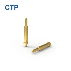
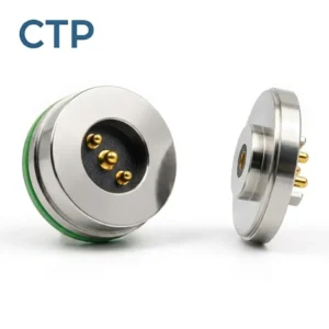
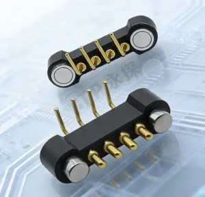
Pogo pin contact force should be specified together with working stroke, tolerance stack-up, pin quantity, mating-pad strength and magnetic holding force. The correct value is not one universal force per pin. It is a force window that keeps every contact electrically stable without overloading the PCB, housing, magnet system or user interface.
Pogo pin contact force cannot be selected from a single catalog number such as 60 grams, 80 grams or 1 newton. The force acting inside a magnetic connector depends on the spring design, actual compression stroke, number of pins, assembly tolerances, magnetic air gap, housing stiffness and external mechanical loads.
A force that works well for one discrete pogo pin may become excessive when multiplied across a 12-pin or 20-pin connector. Conversely, a low-force contact that appears acceptable during a static bench test may become unstable when the device vibrates, the enclosure deflects or the installed working stroke falls below nominal.
This guide explains how engineers can define a pogo pin contact-force window, calculate the total spring load and balance that load against the magnetic holding system.
What Is Pogo Pin Contact Force?
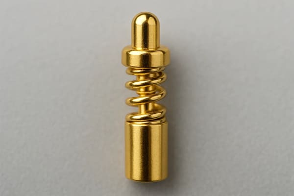
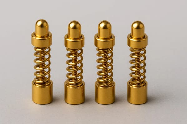
Pogo pin contact force is the axial spring force applied by the compressed plunger against its mating pad.
The force is normally associated with a defined position in the pin stroke, such as:
- Initial contact position
- Minimum working stroke
- Nominal working stroke
- Maximum working stroke
- Full mechanical travel
A force value without its corresponding compression stroke is incomplete.
For example, these two statements do not provide the same level of information:
- Incomplete: Spring force is 0.6 N.
- Useful: Spring force is 0.6 N at 0.7 mm nominal compression, with defined minimum and maximum limits.
The second statement allows the engineer to connect the spring specification to the actual connector assembly.
Why Contact Force Is Not the Same as Magnetic Force
A magnetic pogo pin connector normally contains several separate forces.
| Force | Primary Function | Typical Design Risk |
|---|---|---|
| Pogo pin spring force | Creates normal force at the electrical contact | Too low may reduce stability; too high may increase wear and structural load |
| Magnetic capture force | Attracts the connector halves as they approach | May create uncontrolled sliding or attract nearby metallic particles |
| Magnetic holding force | Maintains the fully mated position | May be insufficient after subtracting spring and seal reactions |
| Seal or gasket reaction | Compresses an enclosure seal | Adds a separating force that the magnets must overcome |
| Housing reaction force | Maintains the mechanical stop and final geometry | Excessive load may deform the housing or PCB |
| External disturbance force | Represents cable pull, vibration or device movement | May temporarily reduce contact compression or separate the connector |
Magnetic force closes and retains the connector. Pogo pin spring force acts in the opposite direction after the pins are compressed.
A connector can therefore have strong magnets but still have insufficient net holding force after all spring and seal forces are included.
The Basic Force Balance of a Magnetic Connector
For a preliminary axial-force review, engineers can use the following simplified model:
Fspring,total = Σ Fi(xi)
Where:
Fiis the spring force of each pogo pinxiis the actual compression stroke of that pinFspring,totalis the combined separating force from all compressed pins
The approximate available connector retention can then be considered as:
Fretention = Fmagnet(g) − Fspring,total − Fseal − Fother
Where:
Fmagnet(g)is the magnetic force at the actual assembled air gapFsealis the reaction force from seals or gasketsFotherincludes other separating loads present in the assembly
This is a first-order engineering model. Final behavior should be verified with the actual housing, magnets, pogo pins, cable and device assembly because magnetic force can change significantly with air gap and alignment.
Step 1: Define the Required Electrical Functions
Begin by identifying the purpose of every contact.
Typical functions include:
- Power input
- Power ground
- Signal ground
- Device detection
- Accessory identification
- Low-speed communication
- Data transmission
- Shielding or chassis connection
Different contacts may not require the same spring force.
For example:
- Power contacts may prioritize stable voltage drop and temperature performance.
- Signal contacts may prioritize resistance stability and controlled mating sequence.
- Detection contacts may use a different length or stroke to establish sequencing.
- Ground contacts may be designed to make before selected signal contacts.
Using one spring specification for every pin simplifies manufacturing, but it should not be assumed to be the optimal electrical architecture.
Step 2: Define the Working-Stroke Window
The nominal pogo pin compression is only one point in the real assembly.
The full dimensional stack-up may include:
- Pogo pin free height
- Pogo pin mounting height
- PCB thickness and position
- Housing height
- Mating-pad position
- Adhesive or overmolding thickness
- Seal compression
- Housing flatness
- Mechanical-stop position
- Magnet position and air gap
- Temperature-related dimensional change
The design should calculate:
| Condition | Required Review | Main Risk |
|---|---|---|
| Minimum compression | Minimum force and electrical stability | Intermittent contact or unequal current sharing |
| Nominal compression | Primary operating force and magnetic balance | Insufficient design margin |
| Maximum compression | Maximum force, over-travel and structural loading | Excessive wear, PCB load or mechanical bottoming |
| Uneven compression | Pin-to-pin force distribution | One contact carrying more current than the others |
The working-stroke window should remain inside the supplier-approved operating range at all assembly extremes.
Step 3: Use the Force-Stroke Curve, Not Only One Force Value
A spring-loaded pin develops increasing force as it is compressed. For initial calculations over a limited working range, the spring may be approximated as:
F(x) ≈ Finitial + kx
Where:
Finitialis the preload or initial spring forcekis the effective spring rate over the selected rangexis the compression from the selected reference position
However, the actual force-stroke behavior should come from the approved pogo pin drawing or measured sample data. Internal spring geometry, friction, plunger guidance and manufacturing tolerance may cause the real curve to differ from a simple linear model.
The drawing or technical agreement should therefore include force limits at more than one position when the tolerance range is important.
Recommended force checkpoints include:
- Force at first electrical contact
- Force at minimum working stroke
- Force at nominal working stroke
- Force at maximum working stroke
Step 4: Calculate the Total Spring Force
The total force increases with the number of compressed pogo pins.
For equal pins operating at equal stroke:
Fspring,total = N × Fpin
Where:
Nis the number of active pogo pinsFpinis the spring force per pin at the actual stroke
For example, six pogo pins producing 0.55 N each create:
6 × 0.55 N = 3.30 N
This 3.30 N acts against the magnetic closing force after the connector is seated.
If manufacturing tolerance increases the force to 0.75 N per pin at the maximum compression condition, the same six pins create:
6 × 0.75 N = 4.50 N
The magnetic design must therefore be reviewed at the maximum spring-force condition, not only at nominal force.
Multi-Pin Connectors Can Create Large Hidden Loads
The force from one small pogo pin may appear insignificant. Multiplication across a multi-pin array can create a substantial connector-level load.
| Pin Quantity | Example Force per Pin | Combined Spring Force |
|---|---|---|
| 2 pins | 0.6 N | 1.2 N |
| 4 pins | 0.6 N | 2.4 N |
| 8 pins | 0.6 N | 4.8 N |
| 12 pins | 0.6 N | 7.2 N |
| 20 pins | 0.6 N | 12.0 N |
These values are illustrative, not universal design recommendations.
As pin count increases, engineers should review:
- Total spring reaction
- Magnetic holding margin
- User separation force
- Housing deformation
- PCB bending
- Pad loading
- Force distribution across the connector face
Step 5: Add Seal, Housing and External Forces
The pogo pins may not be the only components resisting magnetic closure.
Additional reaction forces may come from:
- O-rings
- Foam gaskets
- Elastomer seals
- Flexible housings
- Spring-loaded covers
- Cable bending
- PCB flexure
- Mechanical latches or guides
These forces should be measured or estimated at the actual assembled position.
An illustrative connector force budget may be:
| Force Component | Illustrative Value |
|---|---|
| Six pogo pins at nominal stroke | 3.30 N |
| Seal reaction | 0.70 N |
| Required external holding margin | 1.50 N |
| Minimum magnetic-force target at seated gap | More than 5.50 N before additional design margin |
The actual margin should be established from the application, force tolerance, ageing, temperature and contamination conditions.
Step 6: Specify Magnetic Force at the Real Air Gap
A magnet should not be selected only from a supplier’s maximum surface-pull value.
The magnetic force in the finished connector depends on:
- Magnet material and grade
- Magnet dimensions
- Opposing magnetic structure
- Steel return path
- Air gap
- Housing thickness
- Coating thickness
- Magnet position tolerance
- Angular or lateral offset
- Operating temperature
The force should be measured on the assembled connector, in the intended direction and at the actual seated gap.
Recommended measurements include:
- Initial capture force
- Axial holding force
- Lateral sliding force
- Cable-peel release force
- Force-displacement curve
- Force at maximum assembly gap
- Force after environmental conditioning where required
Stronger Magnets Do Not Automatically Improve Contact Reliability
Increasing magnetic force can create new problems.
Excessive magnetic force may:
- Increase user removal force
- Compress pogo pins beyond the intended stroke
- Increase housing and PCB load
- Cause impact when the connector snaps together
- Increase sliding across the contact pads
- Attract metallic debris to the contact face
- Interfere with a desired breakaway function
The objective is not maximum magnetic force. The objective is sufficient magnetic force at the worst-case assembled condition while maintaining acceptable release behavior.
Step 7: Check Contact-Pad and PCB Loading
The mating pad must withstand the concentrated load from the pogo pin tip.
Important variables include:
- Plunger-tip geometry
- Contact-force level
- Pad material and surface finish
- Pad thickness and support
- PCB construction
- Number and spacing of contacts
- Sliding or wiping distance
- Expected cycle count
- Contamination and environmental exposure
A pointed or crown-shaped tip may create a different contact-pressure distribution from a flat or rounded tip.
Higher local pressure may help penetrate light surface films, but it may also accelerate:
- Pad indentation
- Finish wear
- Scratching
- Exposure of the underlying material
- Wear debris generation
The contact-force specification should therefore be reviewed together with the selected tip and mating-pad geometry.
Step 8: Review PCB and Housing Deflection
The pogo pins apply load to the complete mechanical structure.
Possible load paths include:
- Pogo pin into the target pad
- Target pad into the PCB
- PCB into the enclosure or mounting posts
- Pogo pin barrel into its housing
- Housing into the magnet and mechanical stop
PCB deflection or housing deformation can reduce the actual compression of some contacts while increasing the compression of others.
Review:
- PCB thickness
- Distance to mechanical supports
- Connector position relative to mounting screws
- Housing wall thickness
- Insert retention
- Mechanical-stop stiffness
- Total multi-pin spring load
Where connector load is significant, transfer the reaction into the housing or mechanical frame rather than relying only on solder joints.
Unequal Compression Causes Unequal Electrical Behavior
In a multi-pin connector, all contacts may not operate at the same stroke.
Causes include:
- Housing flatness variation
- PCB warpage
- Magnet misalignment
- Pogo pin free-height tolerance
- Target-pad height variation
- Foreign material on the mating surface
- Angular docking
If several contacts are connected in parallel, unequal compression may create unequal current distribution.
The lowest-resistance contact may carry more current, become hotter and change resistance further. The design should therefore evaluate individual contact channels rather than assuming identical behavior.
Contact Force and Contact Resistance
Increasing contact force can improve contact conformity and resistance stability within a useful operating range. However, force alone does not determine contact resistance.
Resistance is also affected by:
- Contact-tip geometry
- Mating-pad geometry
- Surface finish
- Base and barrier materials
- Contamination
- Wear
- Current level
- Temperature
- Plunger and barrel internal construction
The design objective should be a stable resistance window across the permitted stroke and environment, not the lowest possible force or the highest possible force.
Contact Force for Power and Signal Pins
Power and signal contacts may require different engineering priorities.
| Contact Function | Primary Concern | Force-Design Consideration |
|---|---|---|
| Power contact | Voltage drop, current sharing and temperature rise | Stable compression under load and tolerance extremes |
| Ground contact | Return path and mating sequence | May require controlled early engagement |
| Low-speed signal | Resistance stability and contact bounce | Avoid insufficient minimum force |
| Detection contact | Reliable dock-presence indication | May use a different height or sequence |
| Data contact | Complete channel behavior and signal integrity | Force is only one part of the channel design |
Do not assume that increasing spring force will solve a high-speed data problem. Signal performance also depends on channel geometry, impedance, return path, shielding and the device circuitry.
Temperature Can Change the Force Balance
Temperature may influence several parts of the force system:
- Housing dimensions
- Pogo pin working stroke
- Spring behavior
- Seal stiffness
- Magnetic force
- Adhesive and insert retention
- PCB position
The force budget should therefore be checked at:
- Minimum operating temperature
- Nominal room condition
- Maximum operating temperature
- Storage extremes where permanent dimensional change is possible
A connector that has adequate magnetic retention at room temperature may have less margin after the air gap, seal reaction or working stroke changes.
Dynamic Loads Require More Than Static Force Measurement
A static force value does not prove stable contact during:
- Vibration
- Cable movement
- Device impact
- Thermal expansion
- Repeated docking
- Housing flexure
Dynamic validation may include:
- Continuous contact-resistance monitoring
- Continuity monitoring at an agreed sampling rate
- Force measurement before and after cycling
- Working-height measurement before and after testing
- Visual inspection of the pad wear pattern
- Magnetic-force measurement after conditioning
Contact resistance variation can reveal momentary instability that may not appear in a static resistance measurement.
How to Measure Pogo Pin Spring Force
The measurement method should define:
- Test sample and drawing revision
- Pin mounted individually or inside the connector
- Compression direction
- Compression speed
- Reference height
- Stroke checkpoints
- Force-gauge resolution
- Sample quantity
- Temperature and conditioning state
A practical procedure is:
- Confirm the uncompressed reference height.
- Align the force gauge axially with the plunger.
- Compress to the minimum working stroke.
- Record force.
- Compress to the nominal working stroke.
- Record force.
- Compress to the maximum permitted working stroke.
- Record force and confirm that the pin is not bottoming out.
- Release the pin and verify return movement.
- Compare multiple samples and production lots.
Testing the assembled connector can reveal effects that an individual-pin test may miss, including housing friction, pin-height variation and PCB deformation.
How to Measure Magnetic Holding and Separation Force
The test should identify the force direction because axial, lateral and peel forces may be different.
A connector-level force test should document:
- Magnet and housing revision
- Actual assembled air gap
- Pogo pins installed or removed
- Seal installed or removed
- Pull direction
- Pulling speed
- Peak force
- Force-displacement curve
- Temperature and conditioning state
Testing the magnets without the pogo pins may be useful for component comparison, but it does not represent the net retention of the completed connector.
What Should Be Written on the Connector Drawing?
A useful pogo pin force specification should include:
- Free height
- Total stroke
- Minimum working stroke
- Nominal working stroke
- Maximum working stroke
- Spring-force range at defined stroke points
- Maximum permitted over-travel
- Plunger-tip geometry
- Mating-pad geometry and finish
- Pin-height tolerance
- Connector flatness requirement
- Magnetic holding-force requirement and direction
- Magnetic air-gap requirement
- Separation or breakaway-force requirement
- Applicable inspection and validation method
Do not specify only:
- “Strong spring”
- “60 g force”
- “High magnetic force”
- “Automatic alignment”
- “Low resistance”
These statements do not define a measurable engineering acceptance window.
Recommended Force-Budget Worksheet
| Input | Minimum Condition | Nominal Condition | Maximum Condition |
|---|---|---|---|
| Pogo pin working stroke | Calculated minimum | Drawing nominal | Calculated maximum |
| Force per pin | Supplier minimum | Nominal curve value | Supplier maximum |
| Pin quantity | Number of simultaneously compressed contacts | ||
| Total spring force | Sum at minimum stroke | Sum at nominal stroke | Sum at maximum stroke |
| Seal reaction | Minimum | Nominal | Maximum |
| Magnetic force | Worst-case gap and condition | Nominal seated gap | Maximum possible attraction |
| Net holding margin | Must remain acceptable | Primary design point | Check user-release force |
Common Pogo Pin Contact-Force Design Mistakes
| Design Mistake | Possible Consequence | Better Approach |
|---|---|---|
| Specifying force without stroke | Supplier and customer may evaluate different operating positions | Specify force at defined compression points |
| Using one pin’s force as the connector force | Total load is underestimated | Sum every simultaneously compressed contact |
| Selecting magnets from surface pull alone | Actual seated force may be much lower | Measure force at the assembled air gap |
| Ignoring seal reaction | Connector may not remain fully seated | Include gasket and housing reaction in the force budget |
| Assuming stronger magnets are always better | Removal force, impact and over-compression may increase | Define both holding and release requirements |
| Ignoring PCB deflection | Some contacts may operate below minimum stroke | Support the PCB and evaluate the complete load path |
| Assuming parallel pins share current equally | One pin may carry excessive current | Measure individual channel resistance and current |
| Using one universal 60 g value | Force may be unsuitable for the pin count and housing | Build a project-specific contact-force window |
| Validating only at room temperature | Force balance may change at temperature limits | Review stroke, seal and magnetic margin across the environment |
Engineering Validation Checklist
Pogo Pin Inputs
- Is the complete force-stroke range available?
- Are minimum and maximum force tolerances defined?
- Is the approved working-stroke window documented?
- Is over-travel controlled?
- Is the plunger-tip geometry defined?
Connector-Level Inputs
- Has total spring force been calculated?
- Are all pins compressed simultaneously?
- Has the seal or gasket reaction been measured?
- Has PCB and housing deflection been reviewed?
- Has pin-to-pin height variation been included?
Magnetic Inputs
- Is magnetic force measured at the real assembled gap?
- Is the force direction defined?
- Is there sufficient worst-case holding margin?
- Is user separation force acceptable?
- Has temperature and magnet-position tolerance been reviewed?
Electrical Inputs
- Is resistance measured at minimum, nominal and maximum stroke?
- Are individual parallel contacts monitored?
- Has voltage drop been measured under load?
- Has temperature rise been evaluated?
- Has dynamic resistance variation been reviewed?
Engineering Reference Standards and Examples
The applicable test conditions and acceptance criteria should be defined in the project specification.
- IEC 60512-13-1 — Engaging and separating forces
- IEC 60512-13-2 — Insertion and withdrawal forces
- IEC 60512-2-2 — Contact resistance at specified test current
- IEC 60512-2-3 — Contact resistance variation
- IEC 60512-9-1 — Mechanical operation endurance without electrical load
- IEC 60512-9-3 — Mechanical operation with electrical load
- Mill-Max — Spring-loaded contact mechanical and climatic test report
- Mill-Max — Example spring-loaded pin specifications at mid-stroke
Frequently Asked Questions
What is the correct contact force for a pogo pin?
There is no universal value. The required force depends on the contact geometry, working stroke, electrical function, pin count, mating pad, environmental condition and total connector-force budget.
Is 60 grams of spring force suitable for every magnetic connector?
No. A value near 60 grams-force may appear in some product specifications, but it must be connected to a specific pin, compression stroke and application. In a multi-pin connector, the total force is the sum of all compressed contacts.
Does higher contact force always reduce contact resistance?
No. Higher normal force can improve contact conformity within a useful range, but resistance also depends on materials, plating, contact geometry, contamination, wear and internal pin construction.
How much stronger should the magnets be than the total spring force?
The magnets should provide sufficient force at the worst-case assembled gap to overcome the combined pogo pin force, seal reaction and required external holding margin. The appropriate design margin depends on the application and release requirement.
Can the magnet itself provide electrical contact pressure?
The magnet closes and retains the connector, while the compressed pogo pin provides the local normal force at the electrical contact. Both systems must be designed together.
Why do some pins in a connector carry more current than others?
Parallel contacts may have different resistance because of unequal working stroke, height tolerance, PCB routing, contamination or surface condition. Current sharing should be measured rather than assumed.
Can excessive pogo pin force damage the PCB?
Yes. The combined multi-pin load can bend a PCB, load solder joints, deform the housing or indent the mating pads if the mechanical structure is not adequately supported.
Should contact force be tested before and after life cycling?
For applications where long-term force retention is important, measuring force before and after defined cycling or environmental conditioning can help identify spring, wear or structural changes.
Should spring force be specified in grams or newtons?
Some supplier documents use grams-force, but engineering drawings should clearly state the unit and the corresponding stroke. Using newtons can reduce ambiguity in connector-level force calculations.
Prepare the Inputs for a Pogo Pin Force Review
Before selecting or modifying the spring and magnet system, provide:
- Application and device type
- Pin count and pin map
- Voltage, current and signal functions
- Pogo pin free height and total stroke
- Minimum, nominal and maximum installed height
- Available PCB and housing support
- Mating-pad material and geometry
- Magnet dimensions and arrangement
- Actual assembled magnetic air gap
- Holding and breakaway-force requirements
- Seal or gasket structure
- Expected vibration and cable loading
- Operating-temperature range
- Required validation and production documents
Review available custom pogo pin connector structures, explore the magnetic connector range, access additional connector engineering guides, or submit your drawings and force requirements through the Get Quote & Samples page.
CTP can review the pogo pin working stroke, spring-force window, total connector load, magnet arrangement, mating-pad geometry and mechanical tolerance stack before prototype development. Final force limits, electrical performance and validation criteria should be confirmed in the approved drawing and project specification.
CTP ENGINEERING PATHS
Choose the right path for your project
Move from application requirements to a connector pair, a data-capable cable assembly, or a charging cable configuration. Final specifications are confirmed against an approved drawing and project validation plan.
Magnetic Connectors
Connector geometry, pin layout, mechanical integration and OEM/ODM review.
Engineering overview → 02Magnetic Data Cables
Power and signal allocation, cable exit, interface selection and assembly review.
Cable engineering → 03Magnetic Charging Cables
Browse the complete cable catalog and shortlist a starting structure for customization.
View cable catalog →