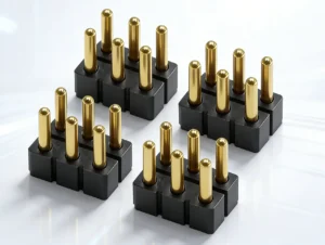
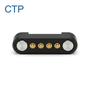
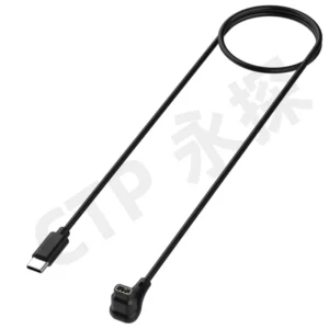
A waterproof magnetic pogo pin interface does not obtain an IP rating from the pogo pin alone. Camera protection depends on the complete device-side feedthrough, housing joints, target inserts, pogo pin mounting, gaskets, adhesives, mechanical stops and electrical control. Engineers must evaluate the interface when it is unmated, approaching, partially seated, fully mated, wet, contaminated and disconnected under foreseeable field conditions.
Outdoor cameras, action cameras, industrial vision systems and removable camera accessories may require power or communication without a conventional deep receptacle.A magnetic pogo pin interface can provide a flush or shallow conductive connection. Magnets may assist attachment, while spring-loaded contacts compensate for a controlled amount of dimensional variation.
This architecture can simplify one part of the external surface, but it does not independently make the camera waterproof.
The complete environmental boundary may still include:- Lens mount or fixed-lens assembly
- Battery and memory-card doors
- Buttons and control dials
- Microphones and speakers
- Display joints
- Viewfinder components
- Sensor or optical windows
- Pressure-equalization vents
- External contact feedthroughs
- Housing seams and adhesives
The magnetic connector should therefore be treated as one enclosure interface rather than the complete waterproofing solution.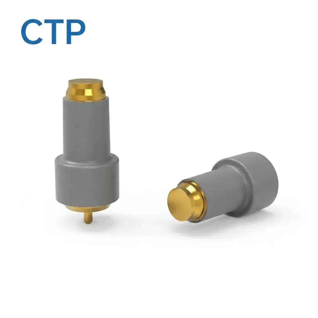
IP Protection Belongs to the Tested Camera or Connector Assembly
An IP classification should identify the exact item that was tested.| Possible Test Item | What the Result Applies To | What It Does Not Automatically Cover |
|---|---|---|
| Individual pogo pin | Specified component-level electrical or mechanical characteristics | Camera enclosure protection |
| Pogo pin connector module | The defined connector module and test configuration | Lens mount, doors, buttons or complete camera |
| Camera-side target insert | The defined feedthrough or insert assembly | Accessory-side sealing and complete camera housing |
| Camera body | The complete tested enclosure in its defined state | Every attached accessory or opened cover condition |
| Camera and attached accessory | The specific mated product combination | Unmated operation or another accessory version |
| Underwater housing | The complete external housing and specified camera installation | The bare camera outside that housing |
“Waterproof pogo pin” should not be used as shorthand for “the finished camera is IP68.” The tested assembly, operating state and acceptance criteria must be identified.
Removing a Deep Port Is Not the Same as Sealing the Camera
A flush target interface may eliminate the depth required by a conventional receptacle, but conductive targets still need an electrical path through or around the camera enclosure.The target-to-enclosure structure may use:
- Insert-molded conductive targets
- Overmolded metal inserts
- Laser-welded metal feedthroughs
- Adhesively bonded target plates
- Overmolded flexible circuits
- Internal potting around the termination
- Targets mounted on an independently sealed external panel
The sealing result depends on the complete joint between the conductive target, housing and internal electrical connection.Define Every Interface State
Camera connector validation should not test only the final fully mated position.| Interface State | Mechanical Condition | Environmental and Electrical Question |
|---|---|---|
| Accessory absent | Camera contacts are fully exposed | Is the camera independently sealed and are the contacts electrically safe? |
| Initial approach | The accessory enters the magnetic field | Can water or debris become trapped between the surfaces? |
| Magnetic capture | The parts move together but are not fully located | Which contacts touch first and is power still disabled? |
| Partial seating | Some contacts or part of the gasket may engage | Can moisture bridge contacts or bypass the incomplete gasket? |
| Fully seated, dry | Mechanical stops and contacts reach nominal position | Does the interface meet electrical and environmental requirements? |
| Fully seated, wet exterior | Water remains around the external joint | Can water migrate into the contact chamber during pressure or movement? |
| Removed during rain | The sealed chamber or targets become exposed | Does the camera remain sealed and does power shut down safely? |
| Remated while wet | Water or residue is trapped between the surfaces | Is wet mating permitted, detected or prohibited? |
| Contaminated interface | Sand, salt, dust or fibres alter the seated position | Does the gasket compress and do the pins remain in their stroke range? |
“Waterproof when connected” and “waterproof when disconnected” are separate requirements.The Camera-Side Seal Should Be Defined Independently
For a removable outdoor accessory, the camera body may need to remain protected even when the accessory or cable is absent.

A robust architecture may separate:- The camera enclosure seal around the target feedthrough
- The electrical contact surfaces exposed outside the camera
- The optional accessory-to-camera perimeter gasket
- The internal pogo pin or target termination
An accessory gasket may protect the active contact chamber while connected, but it should not be the only barrier protecting the camera interior unless that operating limitation is clearly defined.Compare Common Sealing Architectures
| Architecture | Possible Benefit | Primary Limitation |
|---|---|---|
| Sealed flat targets on the camera and pogo pins in the accessory | Camera contains no exposed moving spring contacts | Accessory must control alignment and working stroke |
| Camera-side pogo pins in a sealed insert | Accessory may use simple flat targets | Moving contacts remain permanently exposed on the camera |
| Independently sealed camera targets plus a mated perimeter gasket | Camera remains protected when disconnected and contacts gain extra protection when connected | Requires control of both feedthrough sealing and gasket compression |
| Accessory gasket as the primary seal | May create a protected chamber when fully mated | Camera protection may be lost when the accessory is removed |
| Internal-only connector behind a sealed cover | No permanently exposed electrical contacts | Opening the cover disturbs the environmental boundary |
| External underwater housing feedthrough | Camera can remain inside a separately sealed housing | The housing feedthrough, cable and external accessory become a separate system |
Magnetic Attraction Should Not Be the Only Gasket Clamp
A perimeter gasket requires a controlled final geometry.

Magnetic force may help draw the camera and accessory together, but the final compression should be established by mechanical stops, support faces or a latch.
Magnet-only gasket compression can vary because of:
- Magnet-force tolerance
- Air-gap variation
- Housing thickness
- Gasket thickness
- Gasket hardness
- Temperature
- Gasket compression set
- Contamination on the sealing surface
- Accessory misalignment
- Long-term magnet or adhesive condition
Increasing magnet strength is not a substitute for controlling the final mechanical distance.Separate Capture, Retention and Gasket Compression
| Requirement | Primary Purpose | Recommended Control |
|---|---|---|
| Magnetic capture | Guide the accessory during approach | Magnet layout and approach geometry |
| Final alignment | Place targets and pogo pins within the approved tolerance | Mechanical guides and datums |
| Pogo pin compression | Establish the intended contact force | Mechanical stops and dimensional stack |
| Gasket compression | Create the designed sealing contact | Controlled sealing land and final gap |
| Accessory retention | Resist cable pull, vibration and handling loads | Magnets, latch or structural support |
| Release | Allow intentional removal without damage | Defined removal direction and force envelope |
Develop the Gasket as a Complete Sealing System
The gasket design should define:
- Material family and exact grade
- Cross-section
- Installed height
- Compression range
- Compression set
- Sealing-land width
- Surface roughness
- Joint interruptions
- Corner radii
- Temperature range
- Water and salt exposure
- Cleaning-agent compatibility
- UV and outdoor ageing where applicable
- Assembly method
Fluororubber, silicone or another elastomer may be evaluated, but no one gasket material is universally correct for every camera.

The selected material must be reviewed together with the housing, coating, adhesive, temperature and compression conditions.
Prevent Water from Being Trapped Inside the Contact Chamber
A gasket can seal water out after seating, but it can also trap water that was already present during attachment.Review whether the interface requires:
- A dry-before-connection instruction
- Drainage paths outside the sealing land
- A moisture escape route before final compression
- A delay before electrical power is enabled
- Leakage-current detection
- Temperature monitoring
- An electrical contact verification sequence
A statement that the gasket “forces all water out” should not be made without a tested flow path and representative wet-mating evaluation.Hydrostatic Pressure Changes the Sealing Load
Water exposure at depth is different from rain or splash exposure.

External pressure may act on:- The camera housing
- The target insert
- The accessory housing
- The perimeter gasket
- Housing seams
- Buttons and flexible membranes
- Optical windows
Pressure may improve contact at one surface while opening or deforming another joint.

The complete camera and accessory should therefore be evaluated at the intended pressure, duration, temperature and mechanical state.
Rain Exposure and Underwater Use Are Different Requirements
| Use Condition | Primary Exposure | Design Question |
|---|---|---|
| Light rain | Droplets and intermittent surface wetting | Can water bridge or collect around exposed contacts? |
| Heavy rain with wind | Directional water and repeated impact | Does water reach the gasket or feedthrough under pressure? |
| Splash near water | Large droplets and possible salt residue | Can the interface be cleaned without damaging the contacts? |
| Temporary immersion | Hydrostatic pressure over a defined time | Which product state and depth are permitted? |
| Continuous underwater operation | Pressure, motion, temperature and prolonged exposure | Is the bare camera or an underwater housing being evaluated? |
| High-pressure water jet | High-energy directional water | Which standard and product category apply? |
Passing one water condition does not establish performance under every other condition.Do Not Treat IP68 as One Universal Depth and Duration
Any immersion claim should state:- The tested product
- The applicable standard
- The test depth or pressure
- The test duration
- The water temperature
- The product operating state
- Whether the accessory was attached
- The acceptance criteria
“IP68” alone does not communicate all of these project conditions.Do Not Use IP69K as a Generic Camera Upgrade
A high-pressure or high-temperature water-jet claim should be connected to the applicable standard and equipment category.

When a road-vehicle standard is referenced, its scope should not be silently extended to a professional camera.

The correct documentation should state:- The exact standard
- The tested camera or accessory
- The mounting position
- The nozzle and water conditions
- The operating state
- The pass and failure criteria
Wet Contacts Need a Defined Electrical State
A camera may remain externally sealed while its exposed contacts are still wet.

The electrical system should define whether the contacts are:- Continuously energized
- Normally de-energized
- Current-limited
- Enabled after mechanical seating
- Enabled after accessory identification
- Disabled after leakage is detected
- Disabled after abnormal temperature or resistance
Possible wet-contact risks include:- Leakage current
- Bridging between adjacent contacts
- Electrochemical corrosion
- Localized heating
- Incorrect accessory detection
- Power sequencing faults
Enclosure water resistance and safe wet electrical operation are separate requirements.Galvanic Corrosion Is Only One Saltwater Failure Mechanism
Galvanic corrosion requires dissimilar conductive materials to be electrically coupled in a corrosive electrolyte.

A camera connector exposed to seawater or salt residue may also experience:- General electrochemical corrosion
- Pitting at coating defects
- Crevice corrosion beneath deposits
- Corrosion at exposed underlayers
- Salt-residue leakage
- Fretting corrosion
- Plating wear
- Staining and residue accumulation
The actual mechanism should be determined from the materials, contact pair, electrical state and surface inspection.Saltwater Exposure Requires a Cleaning and Drying Procedure
Salt residue can remain after the visible water has evaporated.The product documentation should define:
- Whether fresh-water rinsing is permitted
- Whether the accessory should remain attached during rinsing
- Whether direct flowing water is permitted
- The approved cleaning agent
- The approved brush, cloth or swab
- Drying time
- Whether doors or covers may be opened
- Inspection requirements before charging or data transfer
“The camera can be confidently washed” should not be published unless the complete product instructions and validation support that procedure.Sand and Silica Create Mechanical as Well as Electrical Risk
A flush interface may be easier to inspect than a deep receptacle, but it is not immune to sand.Sand can:
- Prevent full accessory seating
- Reduce gasket compression
- Scratch the sealing land
- Block pogo pin movement
- Increase side load
- Abrade the target finish
- Remain trapped around magnets
- Create an electrical leakage path when mixed with moisture
The interface should be inspected and cleaned before mating after desert, beach or dusty field use.Vertical Compression Is Not Automatically Self-Cleaning
A pogo pin moving vertically may compress against the same target area with little or no lateral wiping.

Whether contamination is displaced depends on:- Tip geometry
- Target geometry
- Normal force
- Lateral movement
- Particle size
- Particle hardness
- Moisture and residue
The contact motion can also press abrasive particles into the finish.

A self-cleaning claim requires representative contamination, mating and wear testing.
Working Stroke and Gasket Compression Must Be Coordinated
The pogo pins and gasket react against the same final mechanical position.A simplified pogo pin stroke is:
S = Hfree - Hseated

The final seated distance may be influenced by:- Camera housing dimensions
- Accessory housing dimensions
- Gasket thickness
- Gasket compression
- Mechanical-stop position
- Target height
- Pogo pin free height
- Coating thickness
- Debris on the sealing surface
| Condition | Pogo Pin Effect | Gasket Effect |
|---|---|---|
| Final gap too large | Insufficient contact compression | Insufficient sealing compression |
| Final gap nominal | Approved working stroke | Approved gasket compression |
| Final gap too small | Over-compression or spring bottoming | Excessive gasket stress or extrusion |
| Contamination on one side | Unequal pin compression | Local sealing interruption |
Pogo pin working stroke and gasket compression cannot be developed independently.The Accessory Load Should Not Pass Through the Contacts
Camera accessories such as battery grips, monitors, GPS modules, communication modules or external power adapters may apply substantial mechanical load.A preferred structural path is:
Accessory → Support Surfaces or Latch → Camera Housingrather than:
Accessory → Magnets → Pogo Pins → Targets → Camera PCBThe mechanical design should review:
- Accessory mass
- Center of gravity
- Camera movement
- Tripod and gimbal use
- Cable loads
- Vehicle or drone vibration
- Impact and drop conditions
- User twisting during removal
Magnetic Quick Release Does Not Automatically Protect the Camera
A magnetic accessory may detach under one pull direction but remain strongly attached under another.The result depends on:
- Pull direction
- Magnetic retention
- Accessory mass
- Camera mass
- Surface friction
- Mechanical guides
- Cable strain relief
- Gasket friction
Quick-release behaviour should be tested with the complete camera and accessory rather than inferred from magnet force.Specify the Contact Pair Rather Than One Gold Thickness
Environmental performance depends on the pogo pin tip and target together.Define:
- Pogo pin plunger material
- Pogo pin underlayer and contact finish
- Target base material
- Target underlayer and finish
- Working stroke
- Contact force
- Tip geometry
- Surface roughness
- Sliding or wiping movement
- Salt, sand and cleaning exposure
A fixed 1.2 μm hard-gold thickness cannot independently supports contact resistance, corrosion performance or service life.Contact Resistance Must Include Test Conditions
A simplified electrical path is:
    Rpath = Rcamera-PCB + Rtermination1 + Rpogo +
    Rinterface + Rtarget + Raccessory-PCB
The voltage drop is:
Vdrop = I × RpathThe resistive power loss is:
Ploss = I² × Rpath

A contact-resistance statement should identify:- The tested component or full channel
- The test current
- The working stroke
- The target material and finish
- The dry or wet condition
- The sample age
- The measurement method
- The acceptance criteria
“Below 30 mΩ” is not a complete interface specification.Power Delivery Requires Complete Thermal Validation
A camera accessory may draw power for a monitor, transmitter, GPS receiver, battery grip, storage module or other function.Define:
- Operating voltage
- Continuous current
- Peak current and duration
- Inrush current
- Permitted voltage drop
- Permitted temperature rise
- Short-circuit response
- Wet-contact response
- Power sequencing
- Removal under load
Current capacity cannot be assigned from pogo pin diameter, spring material or gold thickness alone.Camera Data and Video Require Defined Physical Channels
Some camera accessories may require:- Low-speed accessory identification
- Shutter or trigger signals
- Sensor communication
- USB data
- Video output
- Storage or recording data
- Timecode or synchronization
These functions have different electrical and protocol requirements.

Pin count and low DC contact resistance do not establish:- USB compatibility
- HDMI compatibility
- Video bandwidth
- Zero latency
- Signal integrity
- Protocol interoperability
High-speed functions require complete channel modelling and testing across the camera PCB, connector, target, accessory PCB and protocol devices.Condensation Is Different from External Water Ingress
A sealed interface can prevent external liquid entry while moisture already inside an enclosure still condenses during temperature changes.Review:
- Assembly humidity
- Internal air volume
- Rapid movement between cold and warm environments
- Pressure-equalization membranes
- Optical-window fogging
- Accessory chamber ventilation
- Moisture trapped during wet mating
Waterproofing and condensation control are related but separate engineering problems.Typical Camera Applications
| Camera Application | Possible Magnetic Interface Role | Primary Engineering Focus |
|---|---|---|
| Action camera charging dock | Charging, detection and project-specific data | Salt, impact, exposed contacts and wet insertion |
| Professional camera battery grip | Power, controls and accessory identification | Structural support, weather sealing and removal under load |
| Industrial vision camera | Power, trigger, control or removable service connection | Dust, washdown, vibration and cable retention |
| Outdoor wildlife camera | External battery, solar or service interface | Long-term weather, condensation and corrosion |
| Drone or gimbal camera module | Removable module power and communication | Mass, vibration, contact stability and magnetic interaction |
| Underwater housing accessory | Feedthrough to lighting, control or external equipment | Pressure, housing penetration and connector state |
| Camera production-test fixture | Programming, calibration and functional testing | Fixture alignment and replaceable probe maintenance |
When May a Magnetic Camera Interface Be Appropriate?
| Project Requirement | Possible Fit |
|---|---|
| Frequent proprietary charging or docking | Magnetic capture may simplify repeated attachment |
| Flush external targets | A sealed target insert may avoid a deep receptacle |
| Controlled camera and accessory ecosystem | Power, identification and project-specific communication can be coordinated |
| One-handed accessory attachment | Magnets can assist approach when mechanical guides set final position |
| Replaceable rugged accessory | A sealed mated chamber may be developed for the defined accessory pair |
When May Another Interface Be Better?
Another solution may be preferable when the project requires:
- Broad USB-C, HDMI or audio accessory compatibility
- Standardized high-speed data without a proprietary cable
- Continuous underwater operation with an existing qualified housing
- No exposed conductive contacts
- Very high accessory structural loads
- Continuous rotation
- Permanent internal connection rather than removable docking
- Field replacement using commonly available cables
Recommended Development Sequence
- Define the camera and accessory operating states.
- Define whether the camera must remain sealed when the accessory is absent.
- Define the applicable ingress or immersion requirement.
- Choose the camera-side and accessory-side contact arrangement.
- Define the independent feedthrough seal.
- Define any perimeter gasket and its compression range.
- Calculate pogo pin minimum, nominal and maximum working stroke.
- Define magnetic capture, retention and removal requirements.
- Complete the electrical Pin Map.
- Define voltage, current, data and wet-contact control.
- Develop salt, sand, cleaning and condensation requirements.
- Build production-intent camera and accessory prototypes.
- Validate every mated, unmated and partial-mating state.
Recommended Validation Plan
| Requirement | Possible Evaluation |
|---|---|
| Seal boundary | Identify the camera feedthrough, accessory gasket and complete enclosure joints |
| Unmated protection | Camera body with no accessory attached |
| Mated protection | Camera with the intended accessory fully installed |
| Partial mating | Tilted, offset, one-side-first and incomplete-gasket states |
| Wet mating | Defined moisture present before attachment |
| Wet unmating | Accessory removal during rain or surface wetting |
| Gasket compression | Minimum, nominal and maximum assembled gap |
| Compression set | Gasket recovery after ageing and prolonged attachment |
| Pogo pin working stroke | Minimum, nominal and maximum compression with gasket tolerance |
| Magnetic force | Capture, retention and removal over production variation |
| Structural load | Accessory mass, cable pull, vibration, impact and user twisting |
| Water ingress | Complete assembly under the applicable water test |
| Pressure exposure | Defined immersion depth, pressure, duration and temperature |
| Rain and directional water | Representative camera orientations and accessory states |
| Saltwater exposure | Representative exposure, cleaning, drying and post-test inspection |
| Sand and dust | Seating, gasket compression, plunger movement and cleaning |
| Wet-contact electrical state | Leakage, short circuit, power control and fault indication |
| Contact resistance | Defined current, stroke, target and environmental condition |
| Voltage drop | Complete power path at the intended current |
| Temperature rise | Maximum load, ambient temperature and mated enclosure state |
| Repeated mating | Project-defined cycles with force, resistance and wear inspection |
| Powered mating | Engagement and separation under the defined electrical load |
| High-speed data | Loss, return loss, crosstalk, eye performance and protocol operation |
| Condensation | Temperature transition and trapped-moisture evaluation |
| Cleaning durability | Approved cleaning procedure followed by sealing and electrical verification |
| Production variation | Contacts, targets, gasket, magnets, housings and assembled gap |
Information Required for an Engineering Review
| Requirement Group | Information to Provide |
|---|---|
| Camera type | Action camera, professional camera, industrial camera, wildlife camera or another device |
| Accessory type | Cable, dock, battery grip, monitor, GPS, transmitter, light or another module |
| Supply scope | Individual contacts, connector pair, magnetic cable or accessory subassembly |
| Protection state | Unmated, mated, both states or underwater-housing use |
| Ingress requirement | Applicable standard, water condition, depth, duration and acceptance criteria |
| Camera geometry | Available area, wall thickness, curvature and restricted regions |
| Contact arrangement | Pogo pins in the camera or accessory and target location |
| Feedthrough structure | Insert molding, adhesive, potting, welding or another process |
| Gasket | Material, cross-section, compression range and sealing surface |
| Working stroke | Minimum, nominal and maximum pogo pin compression |
| Magnetic requirements | Capture, retention, removal direction and magnetic-sensitive regions |
| Mechanical loads | Accessory mass, cable pull, vibration, shock and drop conditions |
| Pin Map | Power, return, detection, identification, data, trigger or service functions |
| Electrical conditions | Voltage, continuous current, peak current and permitted voltage drop |
| Communication | Low-speed control, USB, video or another physical layer |
| Environmental exposure | Rain, saltwater, sand, dust, cleaning agents and temperature |
| Cleaning process | Rinsing, wiping, brush, drying and inspection requirements |
| Durability | Mating frequency, powered separation and acceptance criteria |
| Files | 2D drawings, 3D models, PCB layout, seal section and accessory assembly |
| Commercial | Prototype quantity, production forecast and development stage |
Common Engineering Mistakes
| Mistake | Possible Consequence | Better Approach |
|---|---|---|
| Calling pogo pins IP68 | The tested enclosure and operating state are unclear | Identify the exact tested assembly |
| Calling the interface hermetic | No gas-leak boundary or leak criterion is defined | Use the applicable enclosure or ingress terminology |
| Assuming a deep port prevents waterproofing | Mature sealed-port structures are ignored | Compare complete enclosure architectures |
| Using magnets as the only gasket clamp | Compression changes with tolerance, contamination and ageing | Use mechanical stops and a defined sealing gap |
| Testing only the fully mated state | Unmated and partial-mating leakage paths remain unknown | Validate every connector state |
| Claiming the gasket forces all water out | Water may remain trapped inside the chamber | Define drainage, drying and wet-mating behaviour |
| Claiming instant auto-sealing after removal | The unmated camera-side seal may be undefined | Develop an independently sealed camera feedthrough |
| Calling vertical motion self-cleaning | Particles may be pressed into the plating | Test the actual tip, target and contamination |
| Using one gold thickness to supports corrosion life | Target, porosity, wear and salt exposure are ignored | Test the complete mating pair |
| Calling every saltwater failure galvanic corrosion | The real failure mechanism remains unidentified | Inspect materials, deposits, wear and electrical state |
| Allowing pogo pins to carry accessory loads | Pin, target, PCB or solder-joint damage | Provide an independent structural load path |
| Claiming quick release prevents all damage | Pull direction and product mass remain untested | Test the complete camera, cable and accessory |
| Claiming high-speed data from Pin count | The physical channel and protocol remain unvalidated | Test the complete signal path |
| Using IP69K as a generic camera rating | The standard scope and test procedure may not apply | Name the applicable standard and exact product |
| Recommending fresh-water washing universally | The camera materials and user instructions may not permit it | Publish only the validated cleaning process |
| Publishing ±0.01 mm without a measurement definition | The production capability cannot be verified | Define the feature, datum, gauge and process capability |
Engineering Reference Sources
Final standard editions, product states and acceptance criteria should be confirmed for the actual camera and accessory.-
IEC 60529 — Degrees of protection provided by enclosures
-
ISO 20653 — IP protection for road-vehicle electrical equipment
-
OM SYSTEM — Example of a camera with defined IPX8 water resistance and conventional external interfaces
-
Sony — Waterproof camera seal inspection, saltwater cleaning and maintenance guidance
-
AMPP — Definition and conditions of galvanic corrosion
-
AMPP — Galvanic, pitting, crevice and fretting corrosion mechanisms
-
IEC 60512-2-2 — Contact-resistance measurement using a specified test current
-
IEC 60512-9-1 — Mechanical-operation endurance without electrical load
-
IEC 60512-9-3 — Mechanical operation with a specified electrical load
Frequently Asked Questions
Can a waterproof pogo pin make a camera IP68?
No. The IP classification must apply to a defined and tested connector assembly or complete camera enclosure.Must a camera remove USB-C to become waterproof?
No. A camera may retain covered or sealed conventional interfaces. The complete enclosure and permitted operating state determine its protection.Should the camera remain sealed when the magnetic accessory is removed?
For many outdoor applications, yes. This requires an independently sealed camera-side target or feedthrough rather than relying only on the attached accessory gasket.Can magnets provide the required gasket compression?
Magnets may assist attachment, but mechanical stops should establish the final gap, pogo pin working stroke and gasket compression.Does a perimeter gasket force water out during mating?
Not automatically. Water may remain trapped unless the interface has a defined drainage, escape or drying strategy.Can waterproof camera contacts be connected while wet?
Only when wet mating has been intentionally designed and validated. Enclosure protection alone does not prove safe wet electrical operation.Does vertical pogo pin movement clean sand from the target?
No. It may press abrasive particles into the contact finish. Cleaning behaviour must be tested with representative contamination.Does gold plating prevent saltwater corrosion?
Not independently. Performance depends on the substrate, underlayer, finish coverage, wear, target material, salt exposure and electrical state.Does IP68 mean the camera can withstand high-pressure water jets?
Not automatically. Immersion and high-pressure water-jet tests are different conditions and must be stated separately.What information is required for a waterproof camera connector review?
Provide the camera and accessory models, mated and unmated protection requirements, applicable water test, feedthrough structure, gasket, working stroke, Pin Map, electrical conditions and environmental exposure.Prepare Your Waterproof Camera Interface Project
Review

    custom magnetic connector components

when the camera and accessory require coordinated pogo pins, targets, magnets and housings.

Review

    custom magnetic cable assemblies

when the project requires a finished cable, connector head, wire termination and strain relief.

Review

    pogo pin connector assemblies

when the mechanical structure already provides attachment and magnets are unnecessary.

Additional application and design resources are available through the

    CTP connector engineering guides
.

Submit the camera model, accessory structure, seal section, applicable water condition, Pin Map and electrical requirements through the

    Get Quote & Samples page
.


    CTP can review the connector supply scope, pogo pin arrangement, target geometry, magnetic layout, gasket interface, working stroke and PCB, FPC or cable termination. Final IP classification, immersion depth, saltwater resistance, high-pressure water performance, high-speed communication, camera safety and complete product compliance must be confirmed through approved drawings and project-specific camera-and-accessory validation.
CTP ENGINEERING PATHS
Choose the right path for your project
Move from application requirements to a connector pair, a data-capable cable assembly, or a charging cable configuration. Final specifications are confirmed against an approved drawing and project validation plan.
Magnetic Connectors
Connector geometry, pin layout, mechanical integration and OEM/ODM review.
Engineering overview → 02Magnetic Data Cables
Power and signal allocation, cable exit, interface selection and assembly review.
Cable engineering → 03Magnetic Charging Cables
Browse the complete cable catalog and shortlist a starting structure for customization.
View cable catalog →