It is easier to recognize the right contact when the product has a clear identity. A straight-tail DIP pin, a shouldered contact and a compact dual-row array look different because they serve different board arrangements. Our range gives you those choices without asking every device to use the same contact shape.
That clarity is useful when preparing pogo pin incoming inspection, but it starts much earlier in the product decision. Choosing a defined contact format gives the board, mating targets and assembly a common reference. The receiving check can then confirm the item selected for the device.
Individual spring contacts can follow your product’s target positions
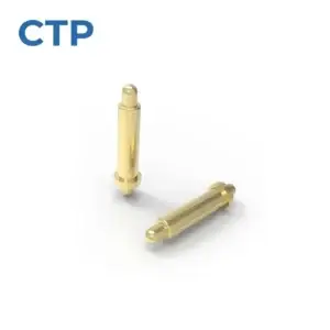
Our through-hole pogo pin, CTP-PP-TH-A01, has a spring-loaded plunger, cylindrical body and straight mounting tail. It provides one electrical contact point, allowing each position to be arranged independently on the board.
For a small instrument with two separated charging pads, that can be more convenient than using a connector block between them. The contact positions follow the targets, while the straight tails connect through the PCB. A housing feature can remain between the pads if the product needs it there.
The straight-tail pin has a recognizable board connection
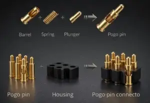
The mounting tail belongs to the fixed board joint, and the plunger belongs to the separable electrical interface. That simple distinction helps both product selection and identification. The contact is chosen with its installed height and mating target in view, rather than treated as a generic metal pin.
The benefit for a product maker is flexibility over the contact layout. Individual pins can serve points that are widely spaced or placed around other components. Their position can be coordinated with the enclosure without requiring one standard contact block to span the whole area.
A shouldered DIP contact adds another body profile
The CTP shouldered DIP contact, CTP-PP-DIP-A02, has a stepped cylindrical body, an upper shoulder and a straight reduced-diameter tail. It is another through-hole format to compare when developing the surrounding support or carrier.
The stepped body can be considered with the device’s support
A shoulder gives the mechanical designer a visible feature within the contact profile. Its actual locating or retaining role is defined in the selected drawing. The useful choice is the different geometry available when a plain cylindrical body does not suit the installation as naturally.
For a module supported above a board, the contact body may need to relate to more than the PCB hole. It may pass through a carrier or sit beside a defined support surface. Comparing the contact profile with those parts can make the installed arrangement clearer from the start.
This also makes a receiving description more meaningful. The selected item is identified by its part and drawing, with a recognizable stepped shape and tail. A similar-looking straight pin is not assumed to be the same component simply because both are spring-loaded contacts.
An integrated array gives several contacts one defined shape
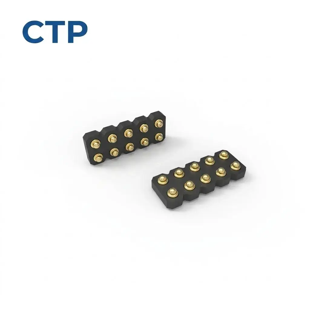
Our ten-contact SMT array, CTP-PC-10P-DR-A01, holds ten spring contacts in a five-by-two housing. It offers a compact contact pattern for a PCB-mounted interface with several assigned electrical paths.
The housing maintains the relative contact positions as one part. That can simplify the layout of a removable control module, where the mating target area needs to align with a group of contacts. The connector has a defined outline to arrange beside the device’s guides and mounting features.
A five-by-two block keeps the contact group together
For an accessory that carries several functions through one mating area, the grouped format can feel more deliberate than multiple separate connection points. Each contact has its own spring action, while the body brings their physical positions into a coordinated arrangement.
That is a product benefit as well as a convenient identification feature. A receiving team can recognize the selected contact count and pattern against the drawing. The same connector identity then carries into the board assembly and matching target design.
Eight contacts offer a shorter dual-row alternative
The CTP eight-contact SMD array, CTP-PC-8P-DR-A01, uses a four-by-two housing. It is worth comparing when the circuit needs eight paths and the available contact area suits that shorter pattern.
A compact device may need to share its board space with a mounting post, sensor or battery connection. A short contact block can be considered alongside those parts while the layout is still being arranged. The target area on the removable part can develop around the same defined pattern.
The array does not decide what the eight paths do. Their functions come from the device circuit. Its advantage is providing independently assigned positions within one compact spring-contact assembly, so the electrical map and product shape can be developed together.
For purchasing and receiving, this is also a reason to retain the exact selected identity. An eight-contact block and a ten-contact block are different interfaces, even when their general construction is similar. A clear description supports the product choice rather than replacing it with a broad category name.
A double-ended contact serves a different kind of module connection
Our long-plunger double-ended contact, CTP-PP-1P-DE-A02, has contact interfaces at both ends, with one end extending farther than the other. It can be evaluated where two facing surfaces sit at different depths.
For a removable sensing module, the extended end may be a useful geometry to compare with a recessed target. The opposite end meets the other conductive surface within the assembly. The part remains one electrical path, with its available movement defined in the chosen drawing.
The two-sided format gives the product another way to create a separable connection. It is a different architecture from a one-sided pin soldered to a board, and that difference deserves to remain clear when describing the supplied component.
Pogo pin incoming inspection can focus on the part you actually selected
A product team comparing individual contacts with an array is also comparing two ways to use board space. Separate DIP pins can leave the area between contact points available for a housing feature. A four-by-two SMD block gathers eight paths into a short rectangular outline. The useful choice follows the product, rather than a rule that every connector should have the same physical format.
For a small charging cradle, the individual through-hole contacts may fit the target positions already chosen on the handheld device. For a removable control module, a shared contact housing may make its mating area easier to coordinate. Both choices provide spring-loaded electrical contact, but they organize the interface differently.
The long-plunger double-ended component introduces another distinction: the connection meets a conductive surface at each end. Keeping that identity clear helps it remain part of the intended module arrangement. Its extended end can be compared with a recess, while the other target and carrier complete the picture.
These visible differences are a benefit during selection because they let the designer compare complete component shapes. They are helpful during receiving for the same reason. The part is associated with a specific target pattern and mounting arrangement, instead of being recognized only as something with a spring inside.
A clear product identity also helps a repeat order begin in the right place. The selected part reference and drawing describe the contact the device uses. Where its geometry or configuration changes, that change is considered with the product. An inspection plan then supports the selected design rather than trying to substitute for it.
Once the contact choice is defined, the receiving review can stay specific. The selected drawing identifies the body and tail geometry, contact pattern and relevant installed references. The product’s agreed acceptance requirements establish the checks; there is no need to borrow one universal limit for every contact style.
For the individual DIP pin, the body and straight tail are part of its board fit. For the shouldered version, the stepped profile is relevant too. For an array, the shared housing and contact layout belong to the assembly. Each item is recognized as the component chosen for that device.
Our spring-contact testing and quality guide gives more detail on evaluation. Using test results and receiving requirements tied to the selected configuration keeps the review relevant to the component that will enter your board assembly.
The main product advantage is the range of defined structures available. You can select the contact around the board, target and enclosure, then keep that choice clear through purchasing and assembly. Incoming inspection becomes a focused confirmation of a deliberate product decision, rather than an attempt to work out what an unidentified contact was meant to do.