Medical, wearable and industrial engineers choose custom magnetic connectors for different reasons. Medical projects may prioritize controlled cable separation, cleanable interfaces and device-level validation. Wearable products focus on limited installation space, frequent charging and exposure to sweat or skin products. Industrial equipment must account for vibration, contamination, mechanical loads and maintenance. A magnetic connector should therefore be designed around the complete device rather than selected only by pin count or appearance.
A magnetic connector is not automatically a better replacement for every USB port, barrel jack or mechanical socket. Conventional connectors remain suitable when their size, mating method and environmental performance meet the product requirements.
Custom development becomes valuable when the connector must fit a specific enclosure, support a defined Pin Map, provide controlled magnetic retention or operate under conditions that cannot be addressed by a standard interface.
Engineers who already know the required contact count, electrical functions and installation structure can review the current
custom magnetic connector catalog
.
One Connector Architecture, Three Different Engineering Priorities
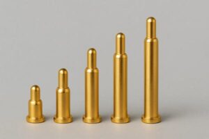
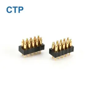
A magnetic pogo pin connector typically combines spring-loaded contacts, mating pads, magnets and a mechanical housing. The same general architecture may be used in a patient monitor, smartwatch or industrial docking station, but the design priorities and validation conditions are not interchangeable.
| Application | Primary Engineering Question | Typical Risks to Evaluate |
|---|---|---|
| Medical devices | How should the interface separate, be cleaned and integrate with the complete equipment? | Unwanted disconnection, excessive cable force, cleaning damage, liquid paths and unsupported compliance claims |
| Wearable devices | How can the charging interface fit the device and remain convenient during repeated daily use? | Limited PCB space, sweat exposure, unstable charging, poor orientation and user-removal difficulty |
| Industrial equipment | How will the connection behave under vibration, contamination, mechanical loading and maintenance? | Intermittent contact, metal particles, cable loading, PCB stress and difficult field replacement |
For this reason, a connector described only as “medical,” “wearable” or “industrial” is not sufficiently defined. The actual electrical, mechanical and environmental requirements must be converted into measurable project inputs.
Medical Devices: Define the Breakaway and Cleaning Conditions
Medical and healthcare equipment may use a connector for charging, sensor attachment, handheld controls or removable accessories. In some applications, accidental cable pulling can transfer force to the equipment, mounting structure or nearby objects.
A magnetic interface can be designed to separate at a selected load, but “breakaway” should not be treated as an automatic safety guarantee. A connector that releases too easily may interrupt charging, communication or device operation. A connector that holds too strongly may transfer excessive force to the equipment.
Define the Complete Separation Event
Engineers should evaluate:- The direction in which the cable may be pulled
- The equipment weight and mounting method
- The required normal retention force
- The acceptable release direction and operator action
- The consequence of an unintended disconnection
- The electrical state while the contacts separate
- Whether the cable or connector can strike another surface after release
The useful requirement is therefore not “strong magnetic force” or “easy breakaway.” It is a defined capture, retention and release behavior for the complete product.
A Flat Interface Does Not Automatically Make the Device Cleanable
A flat contact surface may be easier to access than a deep socket, but cleaning performance also depends on the complete mechanical assembly.
The review should include:
- Gaps between the connector and equipment enclosure
- Contact and housing material compatibility
- The actual cleaning agent, concentration and method
- Possible liquid paths around contacts, magnets and cable exits
- Residue that may remain between adjacent contacts
- The mating and unmated condition during cleaning
- The equipment-level sealing and validation plan
Do not describe a connector as medical-grade, sterilization-resistant or waterproof unless the exact material system, assembled structure and agreed test condition support the claim.
Wearable Devices: Design Around the Charging Journey
Smartwatches, activity trackers, smart rings, hearables, smart glasses and body-worn sensors have limited space for the battery, PCB, antennas, sensors and charging interface.
A custom magnetic connector gives engineers control over the contact arrangement, connector height, housing shape, mating direction and internal PCB or wire connection. However, the design should begin with how the user wears and charges the product, not only with the number of pogo pins.
Confirm the Interface Location Before Finalizing the Connector
A charging interface positioned on the back, side, end or dedicated cradle creates different mechanical and user requirements.
| Interface Position | Questions to Review |
|---|---|
| Device back | Skin contact, sensor windows, curvature, charging cradle and whether the device lies flat |
| Side edge | Product thickness, cable side load, strap interference and accidental pulling |
| Bottom or end | Vertical docking, product balance, cable outlet and need for a locating structure |
| Charging cradle or case | Device positioning, accessory replacement, contact compression and user insertion sequence |
Moving the charging position after the enclosure, battery or PCB has been finalized can create extensive redesign work. Interface placement should therefore be confirmed before final connector dimensions.
Translate User Experience into Measurable Requirements
| User Expectation | Engineering Requirement |
|---|---|
| Easy charging | Permitted approach angle and positional offset |
| Automatic alignment | Defined magnetic capture region and mechanical locating structure |
| Stable charging | Required pogo pin compression and allowable device movement |
| Easy removal | Defined release force, direction and one-handed operation requirement |
| Repeated daily use | Project-specific mating, wear and cleaning validation |
Sweat Resistance Is a Complete Material-System Requirement
Body-worn products may encounter perspiration, skin oils, cosmetics, cleaning agents and moisture. These exposures can affect the mating pads, pogo pin surfaces, housing, adhesives and any gap where liquid can remain.
Engineers should specify the contact location, wearing duration, exercise conditions, cleaning routine and customer-defined exposure test. A plating material or thickness should not be treated as proof of long-term corrosion resistance without representative validation.
For a deeper review of wearable charging frequency, interface position, magnetic docking, breakaway behavior and exposure conditions, continue to the
smart wearable magnetic charging application guide
.
Industrial Equipment: Separate Electrical Contact from Mechanical Support
Industrial connectors may operate around machine vibration, cable movement, dust, oil, coolant, metal particles and repeated maintenance. A connection that performs correctly on a bench may behave differently after cable routing, clamping, operator handling and equipment motion are introduced.
Magnets Should Assist Alignment, Not Carry the Complete Mechanical Load
Magnetic attraction can guide the final mating movement, but the device housing, cradle, guide rails, fixture or mounting structure should normally carry the main mechanical load.

A preferred load path is:

Device enclosure → locating structure → equipment frame

rather than:

Device load → magnets → pogo pins → solder joints → PCB

Allowing equipment weight, cable pull or side load to pass through the pogo pins can produce unstable compression and repeated stress on the PCB or solder joints.
Vibration Resistance Cannot Be Defined by Magnetic Force Alone
Stable operation under movement depends on the combined effect of:
- Mechanical guidance
- Magnetic retention
- Pogo pin working compression
- Spring-force variation
- Cable weight and outlet direction
- Equipment acceleration and vibration direction
- Housing and PCB rigidity
- Contact resistance during movement
Excessive magnetic force may increase seating impact, removal effort and attraction of metallic debris. Insufficient force may allow separation or movement. The correct design must balance capture, retention and release.
Metal Particles Require a Specific Contamination Review
Magnets used near fabrication, machining or maintenance areas may attract steel particles. Conductive debris can interfere with seating, scratch contact surfaces or bridge adjacent contacts.
Possible design responses include:
- Accessible and cleanable mating surfaces
- Contact spacing appropriate to the expected particles
- Shielded or recessed magnetic components
- Controlled power on exposed contacts
- Detection before full operating power is enabled
- Protective covers when the connection is not in use
- Defined inspection and maintenance intervals
For a more detailed review of cable routing, vibration, contamination, strain relief, cleaning and maintenance conditions, use the
industrial magnetic connection application guide
.
Shared Design Decisions Across All Three Sectors
Although the operating environments differ, medical, wearable and industrial projects share several connector-design decisions.
1. Define Electrical Functions Before Selecting the Pin Count
Begin by listing every independent electrical path:
- Power input
- Power return or ground
- Charging detection
- Device identification
- Control or enable functions
- Signal or communication channels
- Reserved contacts where required
Pin count is the result of the circuit allocation. It should not be selected only because an existing connector has the desired appearance.
2. Evaluate Disconnected and Partial-Mating States
The connector does not move directly from fully disconnected to fully seated. During approach or removal, one contact may touch before another, the connector may be tilted or the housing may be retained magnetically without reaching the intended pogo pin compression.
For each credible state, determine:
- Which contacts may touch first
- Whether exposed contacts are energized
- Whether adjacent contacts can be bridged
- Whether reverse polarity or incorrect identification is possible
- How the system detects a valid seated condition
- When operating or charging power is enabled
- How power is removed during disconnection
3. Separate Capture, Retention and Release
“Magnetic force” is often treated as one value, but the connector interaction involves several different requirements:
| Requirement | Engineering Meaning |
|---|---|
| Capture | How the connector responds when it enters the magnetic approach region |
| Alignment | How the connector moves toward the intended mechanical position |
| Retention | How the interface remains seated during normal use |
| Release | The force and direction required for intentional or accidental separation |
4. Define the Complete Protection Boundary
Environmental protection may depend on the mating face, pogo pin mounting, magnet installation, overmolding, cable entry, device enclosure, gasket, drainage and cleaning procedure.
A connector-level protection result should not automatically be treated as the waterproof, corrosion or cleaning performance of the complete customer device.
When Is a Standard Magnetic Connector Sufficient?
| Standard Connector May Be Sufficient When | Custom Development Should Be Considered When |
|---|---|
| The existing dimensions fit the available installation space | The enclosure has a unique shape, curvature or restricted internal depth |
| The existing Pin Map matches the circuit | Power, signal, detection or identification require a project-specific layout |
| The standard mounting method fits the PCB or cable architecture | The project requires a specific PCB, FPC, wire or cable termination |
| The standard retention behavior is acceptable | Capture, holding and release behavior must be tuned to the device |
| The environment is moderate and clearly defined | The product encounters sweat, chemicals, vibration, debris or repeated cleaning |
| No special mating sequence is required | The circuit requires detection, authorization or controlled power sequencing |
When the correct contact count or connector structure is still uncertain, use the
magnetic pogo pin connector selection guide
before choosing a product category.
Information Required Before Engineering Review
| Requirement Group | Information to Provide |
|---|---|
| Application | Device type, use case and operator interaction |
| Electrical | Voltage, continuous current, peak current, Pin Map and signal functions |
| Mechanical | Available length, width, height, mating direction and device support structure |
| Magnetic behavior | Required capture, retention, accidental-pull and intentional-release behavior |
| Installation | PCB, wire, FPC, cable or other termination method |
| Environment | Sweat, water, dust, metal particles, oil, chemicals, vibration and temperature |
| Validation | Required test method, operating state and acceptance criteria |
| Commercial | Prototype quantity, expected annual volume and development schedule |
| Files | 2D drawings, 3D models, PCB layout and enclosure information |
Common Engineering Mistakes
| Mistake | Possible Consequence | Better Approach |
|---|---|---|
| Selecting only by pin count | The electrical contacts fit, but the mechanical or circuit requirements do not | Define the Pin Map, installation space and mating behavior first |
| Maximizing magnetic force | Difficult removal, high seating impact or excessive equipment load | Define capture, retention and release separately |
| Assuming the connector is automatically waterproof | Liquid enters through the device or mounting interface | Validate the complete assembled protection boundary |
| Ignoring partial mating | Unstable power, short circuit or incorrect device detection | Evaluate tilted, offset and one-contact-first states |
| Using pogo pins as mechanical supports | PCB, solder-joint or contact damage | Transfer equipment loads through the housing or locating structure |
| Publishing unverified current, life or environmental values | The claim does not match the final structure or operating condition | Define the test sample, method, state and acceptance criteria first |
Frequently Asked Questions
Why do medical devices use custom magnetic connectors?
A custom structure may provide controlled cable separation, a more accessible mating surface and integration with a specific equipment enclosure. Final suitability depends on the device risk analysis, cleaning process, electrical state and complete assembly validation.
Why are magnetic connectors suitable for wearable charging?
They can be designed around limited enclosure space and a simplified charging interaction. The interface position, device weight, sweat exposure, cleaning method and repeated-use conditions must still be evaluated.
Can magnetic connectors be used in vibrating industrial equipment?
Yes, but magnetic retention alone does not establish vibration resistance. Mechanical guidance, pogo pin compression, cable load, mounting and the complete equipment profile should be tested together.
Are custom magnetic connectors automatically waterproof?
No. Final protection may depend on the connector housing, pogo pin mounting, overmolding, cable entry, customer enclosure and agreed test condition.
Can one magnetic connector carry both power and signals?
It may be possible to assign separate contacts for power, return, detection, control and signal functions. The final Pin Map should be reviewed according to current, signal, spacing and mating-sequence requirements.
What should be provided for a custom magnetic connector quotation?
Provide the application, Pin Map, voltage, current, installation space, mating direction, magnetic behavior, environmental conditions, termination method, expected quantity and available drawings.
Continue Your Connector Evaluation
Browse the
current magnetic connector range
after the required pin functions and installation structure have been confirmed.
For a project-specific review, submit the electrical requirements, mating structure, operating environment and available drawings through the
Get Quote & Samples page
.
CTP ENGINEERING PATHS
Choose the right path for your project
Move from application requirements to a connector pair, a data-capable cable assembly, or a charging cable configuration. Final specifications are confirmed against an approved drawing and project validation plan.
Magnetic Connectors
Connector geometry, pin layout, mechanical integration and OEM/ODM review.
Engineering overview → 02Magnetic Data Cables
Power and signal allocation, cable exit, interface selection and assembly review.
Cable engineering → 03Magnetic Charging Cables
Browse the complete cable catalog and shortlist a starting structure for customization.
View cable catalog →