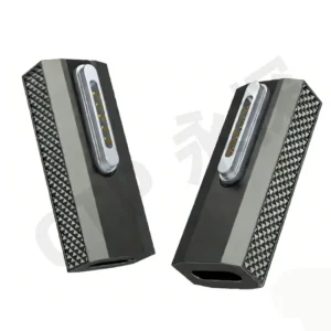
Custom magnetic connectors can support sleek product architectures by
replacing a deep insertion interface with a removable surface contact
system. However, visual simplicity does not mean engineering simplicity.
The connector, magnets, pogo pin working stroke, PCB routing, mechanical
datums, enclosure surfaces and accessory geometry must be designed as one
system. A successful magnetic interface should therefore be evaluated by
its complete three-dimensional package and user interaction rather than
connector thickness alone.
What Does a “Sleek” Connector Architecture Actually Mean?
In industrial design, a sleek product is not simply a thinner product.The perceived quality of a device can be influenced by the number of visible
openings, surface interruptions, mechanical latches, exposed fasteners,
connector cavities and accessories required around the enclosure.
This is why connector architecture can influence the visual language of a
product even though the connector itself occupies only a small part of the
complete assembly.
A custom magnetic connector can allow engineers to move from a conventional
deep plug-and-receptacle architecture toward a relatively shallow removable
contact interface.That can affect:
- external surface continuity;
- product thickness distribution;
- charging-interface placement;
- accessory attachment;
- user interaction;
- module replacement;
- internal PCB and enclosure packaging.
The important engineering principle is:


    A sleek product is a system-level packaging result, not a property that
    can be created by selecting a “thin connector” in isolation.
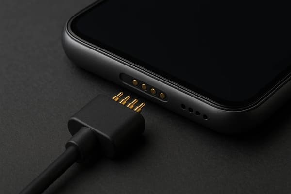
for contacts, magnets, PCB routing, mechanical support and working stroke.
Start with the External Surface — Then Work Inward
Conventional receptacles normally require an opening in the enclosure and
sufficient internal depth for the connector body, solder joints and cable or
PCB transitions.

A custom magnetic interface can change that relationship.

Instead of inserting a plug deeply into the device, the removable half can
approach a surface containing conductive targets or spring-loaded contacts.

This can make it possible to create:- flush or near-flush charging surfaces;
- underside docking interfaces;
- hidden accessory interfaces;
- side-mounted removable modules;
- charging contacts integrated into a product stand or cradle.
The advantage is not that a magnetic connector eliminates structure.

It gives the product team a different way to distribute that structure.
A Flush Interface Still Has a Hidden Z-Stack
One of the biggest mistakes in early product design is evaluating only the
visible contact surface.

Behind that surface, the connector may still require:- pogo pin free height;
- working compression;
- pogo pin barrel length;
- PCB thickness;
- solder or termination height;
- magnet thickness;
- magnet retention structure;
- mechanical stops;
- housing wall thickness;
- target support structure;
- PCB trace or FPC routing.
Therefore, the correct comparison is not:

USB connector height vs. pogo pin height.
It is:
    Complete conventional interface envelope vs. complete magnetic interface
    envelope.
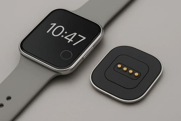
connector and enclosure Z-stack rather than the visible contact height alone.
Low Z-Height Can Create New XY Routing Problems
Making an interface shallower does not necessarily reduce the total amount
of internal space required.

When the available vertical space becomes smaller, engineers may need to
distribute magnets, contacts, traces and mechanical supports across a larger
horizontal area.
This can create new constraints around:
- PCB routing channels;
- antenna keep-out areas;
- battery placement;
- speaker and microphone cavities;
- camera modules;
- thermal spreaders;
- fasteners;
- structural ribs.
For this reason, the magnetic connector should be reviewed early in the
complete product layout rather than added after the PCB and enclosure are
already frozen.
Magnetic Capture Is Part of the User Experience
A conventional connector normally communicates mating through insertion
force, latch engagement or a mechanical stop.

A magnetic interface creates a different interaction.

As the accessory approaches the device, magnetic attraction can begin before
physical electrical contact is established.

This creates a sequence that the user can feel:


    Approach
    →
    Magnetic Capture
    →
    Guided Seating
    →
    Contact Compression
    →
    Fully Seated Interface


Industrial designers and mechanical engineers should therefore treat the
magnetic-force profile as part of the interaction design, not merely as a
connector specification.
“Snap” Quality Is Not the Same as Maximum Magnetic Force
A stronger magnet does not automatically create a more premium user
experience.
Excessive attraction can create:
- aggressive closing impact;
- greater finger effort during removal;
- higher housing load;
- more lateral sliding before final seating;
- reduced breakaway behavior;
- greater attraction of ferromagnetic debris.
A good design instead balances approach behavior, seated retention and
removal.
Capture, Retention and Release Should Be Designed Separately
| Interaction Stage | Engineering Question |
|---|---|
| Capture | From what approach distance and offset should attraction become useful? |
| Final Seating | What mechanical features establish the final connector position? |
| Retention | How much normal user movement should the interface tolerate? |
| Axial Removal | How much force should straight removal require? |
| Peel Release | Should lifting one edge release the module more easily? |
| Off-Axis Load | How should the interface behave when pulled or twisted sideways? |
These parameters influence both user experience and structural reliability.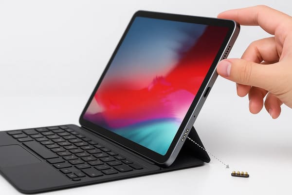
positioning, contact compression and accessory-removal behavior.
The Magnet Should Not Be the Final Precision Datum
Magnetic attraction can help a user bring the mating halves together, but
it should not normally be responsible for determining the final electrical
position.

A more controlled architecture separates the functions:| Function | Preferred Design Element |
|---|---|
| Initial Capture | Magnetic system |
| Orientation | Housing shape or mechanical coding |
| Final X-Y Position | Mechanical datums |
| Final Z Position | Mechanical stop |
| Electrical Compliance | Pogo pin working stroke |
| Normal Retention | Magnetic and mechanical structure |
This becomes particularly important when several contacts must reach similar
compression at the same time.
Working Stroke Belongs in the Industrial-Design Stack-Up
Pogo pin movement is often treated as an electrical detail, but it directly
influences product dimensions.

After the accessory reaches the mechanical stop, each pogo pin should remain
within the approved working range.
A simplified relationship is:
S = Hfree - Hseatedwhere:
- S is pogo pin compression;
- Hfree is the installed free height;
- Hseated is the height after complete mating.
This means enclosure dimensions, PCB location, target height and mechanical
stops directly affect the electrical interface.
A Sleek Interface Requires Cross-Functional Tolerance Design
The final working stroke may be influenced by:- PCB thickness;
- connector installed height;
- solder height;
- housing tolerance;
- module flatness;
- target-pad height;
- mechanical-stop location;
- assembly variation.
Industrial design, mechanical engineering and electrical engineering
therefore cannot develop the interface independently.
The Mating Target Is Also Part of the Exterior Design
In many magnetic connector architectures, the device-side target remains
visible when no cable or accessory is attached.

This means its engineering decisions can also affect the visual product
surface.
The target may need to balance:
- electrical contact area;
- pogo pin positional tolerance;
- surface finish;
- wear;
- cleanability;
- corrosion exposure;
- color and appearance;
- integration with surrounding housing materials.
The target should therefore not be treated as an electrical pad added after
the exterior surface has already been designed.
Surface Simplicity Can Improve Cleanability — But Creates New Exposure
A relatively flat contact surface can avoid some deep cavities where dirt
may accumulate.

That can be useful for products that are frequently handled, docked or
cleaned.

However, the contacts themselves may remain exposed when the accessory is
removed.
This creates a different design problem involving:
- skin oil;
- sweat;
- dust;
- liquid droplets;
- cleaning agents;
- foreign conductive objects;
- metallic debris attracted by magnets.
A cleaner-looking surface is therefore not automatically a lower-risk
electrical interface.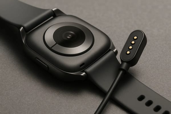
contacts, moisture, sweat and the complete sealing boundary still require
engineering validation.
Flush Contacts Do Not Automatically Create a Waterproof Product
Removing a conventional receptacle opening can simplify part of the
enclosure architecture.

It does not automatically establish any particular ingress-protection
rating.
The sealing boundary may still include:
- pogo pin feedthroughs;
- connector-to-housing joints;
- target-pad mounting;
- gaskets;
- insert molding;
- potting;
- PCB or FPC transitions;
- other openings elsewhere in the product.
Mated and unmated environmental states may also be different.Custom Magnetic Connectors Can Define a Module Boundary
One of the more valuable uses of a custom magnetic interface is not simply
charging.

It can define where one functional module ends and another begins.
For example:
- a tablet and keyboard;
- a wearable device and charging cradle;
- a sensor body and replaceable battery;
- a handheld terminal and docking station;
- a headset and removable accessory;
- a product body and service module.
The connector then becomes part of the product architecture rather than only
an electrical component.
A Good Module Boundary Needs an Interface Contract
Once the connector separates two product modules, the engineering team
should define exactly what crosses that boundary.| Interface Layer | Questions to Define |
|---|---|
| Mechanical | How is the module located, retained and removed? |
| Power | What voltage, current and power sequencing are required? |
| Signals | What control or data paths cross the interface? |
| Detection | How does the host know the module is present? |
| Identification | Does the system need to identify which module is attached? |
| Environment | What happens when the interface is exposed and unmated? |
| Service | Which component should be replaceable if the interface wears? |
Removable Does Not Automatically Mean Hot-Swappable
Magnetic attachment can make a module easy to remove physically.

Hot-swap capability is a separate system function.
It may require:
- module detection;
- controlled power sequencing;
- power-path switching;
- current limiting;
- hold-up energy;
- firmware state management;
- fault handling.
The connector provides the physical interface; the electronic architecture
determines whether live removal is safe and functional.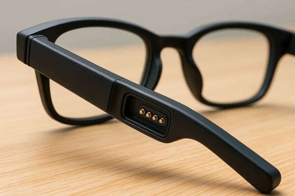
mechanical, electrical and system-level boundaries are deliberately defined.
Electrical Architecture Should Follow the Product Function
A custom magnetic connector can allocate contacts according to the actual
product requirements.
A Pin Map may include:
- power;
- power return;
- module detection;
- identification;
- control signals;
- project-specific communication;
- service or diagnostic contacts.
This flexibility is useful because the visible connector shape does not need
to dictate one fixed electrical architecture.
Pin Count Does Not Define Data Capability
Adding contacts does not automatically create a high-speed data interface.Signal capability can depend on:
- signal and return allocation;
- contact geometry;
- pitch;
- PCB transitions;
- cable construction;
- reference-plane continuity;
- crosstalk;
- complete channel length.
A specific high-speed protocol should therefore be evaluated through the
complete electrical channel.
Charging Performance Is Also a System Property
Compact contacts can form part of a charging interface, but fast charging
should not be inferred from connector appearance or pin diameter alone.
A complete power path can include:
    Power Source
    →
    Cable / PCB
    →
    Connector Termination
    →
    Pogo Pin
    →
    Contact Interface
    →
    Target
    →
    Device PCB
    →
    Power Electronics
The complete path influences:
- voltage drop;
- power loss;
- temperature rise;
- current sharing;
- charging stability.
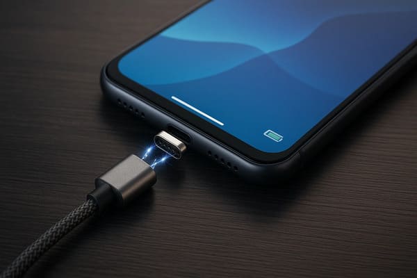
electrical and thermal validation for the intended product.
Sleek Design Also Means Designing the Empty State
Product teams often focus on how the device looks when the charging cable or
accessory is attached.

For a removable interface, the opposite condition may be more common:

The accessory is absent.

The empty-state design should consider:- appearance of exposed contacts;
- finger accessibility;
- potential contact with conductive objects;
- cleanability;
- liquid exposure;
- foreign-object accumulation;
- whether power remains present on exposed contacts.
A visually clean interface should also have a defined electrical behavior
when nothing is attached.
Magnetic Attachment Does Not Mean Immediate Power Enable
The connector can begin magnetic capture before all required electrical
contacts have reached the final working position.

A product may therefore experience:- one contact touching before another;
- partial seating;
- connector tilt;
- debris preventing full engagement;
- temporary contact during removal.
Where the electrical risk justifies it, detection and power-enable logic
should be separated from the physical magnetic attachment.
Industrial Design Should Include Breakaway Direction
For cables and removable accessories, the direction in which the user pulls
matters.

Straight axial separation can require substantially different mechanical
behavior from lifting or peeling one side of a connector.

The industrial-design team can therefore influence breakaway performance
through:- connector location;
- edge geometry;
- cable exit direction;
- finger-access areas;
- housing curvature;
- magnet distribution.
Breakaway is therefore not only a magnet-selection problem.Custom Magnetic Connectors Trade Standardization for Design Freedom
One major reason to develop a custom connector is the ability to adapt the
mechanical and electrical interface around the product.

The trade-off is reduced compatibility with standardized third-party
ecosystems.| Custom Magnetic Interface | Standard Connector |
|---|---|
| Geometry can follow the product | Product normally follows standardized connector geometry |
| Custom Pin Map possible | Pin assignment usually predefined |
| Magnetic retention can be customized | Retention architecture already defined |
| Accessory ecosystem may be proprietary | Broader third-party compatibility may be available |
| More integration freedom | Less custom engineering required |
If universal interoperability is more important than enclosure integration,
a standardized connector may still be the better choice.
Manufacturability Must Be Designed with the Product
A visually clean interface can become difficult to manufacture if its
tolerances are established without considering production processes.
Manufacturing review may need to include:
- connector mounting method;
- PCB footprint;
- pogo pin installed height;
- magnet polarity control;
- magnet position;
- housing molding tolerance;
- assembly sequence;
- adhesive or insert-molding process;
- target coplanarity;
- inspection access.
SMT Compatibility Should Be Confirmed, Not Assumed
Some pogo pin and magnetic connector structures can be designed for
surface-mount assembly.

However, SMD termination or tape-and-reel packaging alone does not ensure compatibility with every production line.
A proper review can include:
- pick-up surface;
- component center of gravity;
- nozzle accessibility;
- carrier orientation;
- solder pad geometry;
- reflow compatibility;
- post-reflow installed height;
- coplanarity.

enclosure integration to be considered together during development.
When Does a Custom Magnetic Connector Make Sense?
| Product Requirement | Why a Custom Magnetic Interface May Be Useful |
|---|---|
| Clean External Surface | Can reduce reliance on a deep user-facing receptacle |
| Frequent Charging / Docking | Supports repeated removable connection |
| Blind Mating | Magnetic capture can improve approach behavior |
| Removable Accessories | Can define a compact mechanical and electrical module boundary |
| Controlled Breakaway | Retention and release behavior can be designed around the product |
| Custom Pin Map | Power, detection and signal functions can be allocated around the application |
| Product-Specific Geometry | Connector shape can follow the enclosure architecture |
When May a Standard Connector Be the Better Design?
A custom magnetic connector should not be selected only because it looks
cleaner.
A standardized connector may remain preferable when:
- third-party interoperability is essential;
- positive mechanical locking is required;
- the interface rarely disconnects;
- a standardized high-speed protocol is the primary requirement;
- extremely high contact density is needed;
- the environment contains difficult-to-control metallic debris;
- development cost or custom tooling cannot be justified.
Design Review Checklist for a Custom Magnetic Connector
| Design Layer | Information to Define |
|---|---|
| Industrial Design | Visible surface, connector location, accessory direction and empty state |
| 3D Envelope | Available X, Y and Z space |
| Mechanical | Datums, guides, mechanical stop and tolerance stack |
| Pogo Pin | Working stroke and required contact force |
| Magnetic System | Capture, retention, removal and breakaway behavior |
| Electrical | Voltage, current, Pin Map and signal requirements |
| Target | Geometry, finish, flatness and allowable wear |
| Environment | Water, sweat, dust, oils and metallic debris |
| Lifecycle | Expected mating profile and end-of-life criteria |
| Manufacturing | PCB mounting, magnet assembly, inspection and tolerance capability |
| Service | Cleaning, replacement and accessory compatibility strategy |
Frequently Asked Questions
Why are custom magnetic connectors useful for sleek product designs?
They can replace a deep insertion interface with a relatively shallow
removable contact surface, giving product teams more freedom to integrate
charging, docking or accessory connections into the enclosure.
Do magnetic connectors automatically make a product thinner?
No. The complete connector still requires contacts, magnets, PCB routing,
working stroke and mechanical support. Engineers should compare complete
three-dimensional interface envelopes rather than visible connector height.
Can magnets precisely align the connector?
Magnets can assist capture, but mechanical datums and guides should normally
control final X, Y, Z and angular position.
Are magnetic connectors zero-insertion-force?
A magnetic interface can avoid conventional plug insertion, but the pogo
pins still require compression and the magnetic interface still generates
mechanical forces. “Zero force” is therefore not an accurate universal
description.
Can custom magnetic connectors make a device waterproof?
They can be incorporated into a sealed enclosure architecture, but final
ingress protection depends on the complete connector feedthrough, housing,
seals, targets and device assembly.
Are custom magnetic connectors suitable for fast charging?
They can form part of a charging interface, but charging capability depends
on the complete electrical resistance path, temperature rise, working
stroke, contact layout and system electronics.
Can custom magnetic connectors support data?
Yes, project-specific signal paths can be designed, but a particular data
rate or protocol cannot be inferred from pin count alone. Complete-channel
validation may be required.
Are magnetic modules automatically hot-swappable?
No. Removable mechanical attachment is different from electrical hot-swap
capability, which requires detection, power sequencing and system-level
control.
Are stronger magnets better for premium product feel?
Not necessarily. Excessive magnetic force can increase removal effort,
closing impact, housing stress, lateral sliding and metallic-debris
attraction.
When should a standard connector be used instead?
A standard connector may be preferable when interoperability, positive
locking, standardized high-speed performance or low custom-development cost
matters more than enclosure-specific integration.
What information is needed to design a custom magnetic connector?
Provide available X-Y-Z space, connector location, Pin Map, voltage,
current, signal requirements, working stroke, mating direction, retention
and breakaway expectations, environmental conditions and product drawings.
Request a Custom Magnetic Connector Engineering Review
Explore

    custom magnetic connector solutions

for charging, docking and removable product interfaces.

Review

    pogo pin and spring-contact solutions

for different contact layouts and mounting structures.

Learn more about CTP manufacturing and development capabilities on the

    About Us page
.

Submit the product envelope, Pin Map, voltage, current, working stroke,
mating direction, magnetic behavior and 2D or 3D design files through the

    Get Quote & Samples page
.


    CTP can review connector geometry, pogo pin working stroke, mating
    targets, magnetic capture, seated retention, breakaway behavior and PCB,
    FPC, wire or cable integration for custom magnetic connector projects.
    Final product thickness, charging capability, signal performance,
    environmental protection and lifecycle depend on the complete product
    architecture and project-specific validation.
CTP ENGINEERING PATHS
Choose the right path for your project
Move from application requirements to a connector pair, a data-capable cable assembly, or a charging cable configuration. Final specifications are confirmed against an approved drawing and project validation plan.
Magnetic Connectors
Connector geometry, pin layout, mechanical integration and OEM/ODM review.
Engineering overview → 02Magnetic Data Cables
Power and signal allocation, cable exit, interface selection and assembly review.
Cable engineering → 03Magnetic Charging Cables
Browse the complete cable catalog and shortlist a starting structure for customization.
View cable catalog →