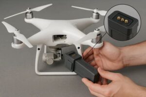
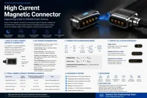
Magnetic connector applications should be evaluated by interface duty,
not by industry name alone. The same magnetic pogo pin architecture can
solve very different problems depending on whether the product needs
low-effort user mating, a cleanable removable surface, autonomous docking,
a serviceable vehicle module or field-replaceable IoT hardware. In every
case, magnetic capture is only one part of the interface; mechanical
positioning, pogo pin working stroke, electrical validation, environmental
exposure and connection-state control must still be designed separately.
Magnetic Connector Applications Are Defined by Interface Duty
It is easy to describe magnetic connectors by listing industries:
consumer electronics, medical devices, vehicles, robots and IoT products.

That approach is useful for market overview, but it does not explain why an
engineer should actually choose the architecture.

A stronger question is:


    What does this interface need to do that a permanently retained or
    conventional plug-and-receptacle connector does not?


Common interface duties include:- frequent removable charging;
- blind or one-handed mating;
- automatic machine docking;
- controlled breakaway;
- cleanable external contact surfaces;
- field-replaceable modules;
- custom combinations of power, detection and selected signals.
Magnetic pogo pin connectors become most valuable when one or more of these
duties creates real product-level value.

The basic interface can be separated into four functions:


    Magnetic System
    =
    Capture + Retention


    Mechanical Structure
    =
    Guidance + Datum + Final Position


    Pogo Pin
    =
    Electrical Contact + Z-Axis Compliance


    System Electronics
    =
    Detection + Validation + Power / Signal Control


The following five industries illustrate how these functions are combined
differently depending on the actual interface problem.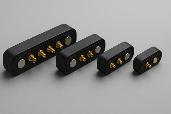
while solving very different interface problems across product
categories.
Application 1: Consumer Electronics — Reduce User Mating Effort
In consumer electronics, the strongest reason to consider a magnetic
connector is often not electrical performance.

It is the way the user interacts with the product.

A wearable, charging case or portable accessory may be connected and
disconnected every day.

In this type of product, the interface may need to support:- one-handed attachment;
- blind or low-visibility mating;
- compact external geometry;
- frequent connection cycles;
- controlled cable breakaway.
The main engineering value is capture
Magnetic attraction can reduce the precision required during the user's
final approach.
A typical sequence can be:
    User Approaches
    →
    Magnetic Capture
    →
    Mechanical Guidance
    →
    Final Seating
    →
    Pogo Pin Compression


Magnets should not be expected to define final precision alignment by
themselves.

Mechanical datums, guide surfaces and stops should normally establish the
final X-Y-Z position.
The interface can also support intentional breakaway
For a cable-side connection, the product designer can define whether the
interface should release before a larger cable load is transferred into the
device.

However, breakaway is not a “zero-force” event.
It depends on:
- magnet arrangement;
- pull direction;
- peel angle;
- spring reaction;
- cable geometry;
- housing design.
Where magnetic may not add much value
If the connection is internal, permanent or rarely accessed, magnetic
capture may add cost and package area without materially improving the
product.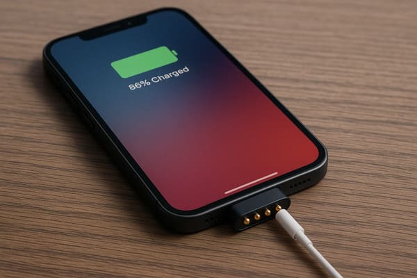
mechanical geometry still defines the final contact position.
Application 2: Medical Devices — Create a Cleanable and Removable Interface Boundary
Medical equipment introduces a different engineering problem.

The value of a magnetic pogo pin interface may come from creating a shallow,
removable external boundary that is easier to access, inspect or clean than
some deep receptacle geometries.
Potential applications can include:
- portable diagnostic instruments;
- charging docks;
- removable sensor modules;
- handheld equipment;
- service or data interfaces.
Flush geometry can simplify cleaning—but does not prove cleanability
A relatively flat target surface may reduce deep cavities where residue can
accumulate.

However, the actual cleanability of a medical device also depends on:- housing geometry;
- gaps and seams;
- surface materials;
- cleaning chemicals;
- exposed-contact design;
- complete device cleaning procedure.
A flat magnetic connector should therefore not be described as
“sterilizable” merely because its surface is shallow.
Material choice does not prove biocompatibility
Contact plating, housing resin or metal selection can be important, but
material names alone do not establish biocompatibility or suitability for
a particular medical application.

The required evidence depends on the actual contact location, exposure and
product risk classification.
Connection state can matter more than convenience
A removable medical interface may need to distinguish:


    Captured
    ≠
    Fully Seated
    ≠
    Electrically Valid


If partial mating could affect product operation, the Pin Map may include
detection or identification functions so that the system can validate the
connection before enabling the required function.
Where magnetic may not be appropriate
A positively locked connector may be preferable when unintended separation
cannot be tolerated or where the interface must remain mechanically secure
under defined clinical use conditions.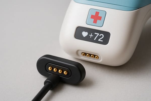
material compatibility and connection control separately from magnetic
convenience.
Application 3: Industrial Automation and Robotics — Enable Autonomous Docking
Industrial automation creates one of the clearest technical use cases for
magnetic pogo pin connectors.

The interface may need to connect without a person manually inserting a
cable.
Examples can include:
- AGV charging docks;
- AMR docking stations;
- robot end modules;
- automated test fixtures;
- removable industrial equipment modules.
The robot should not rely on the connector to correct large positioning errors
A robust docking architecture separates positioning responsibilities:


    Robot / Dock
    →
    Gross Position
    →
    Mechanical Guidance
    →
    Magnetic Capture
    →
    Mechanical Seating
    →
    Pogo Working Stroke


The dock geometry should handle large positioning variation.

Magnets can assist final capture.

Mechanical stops should define final position.

Pogo pins then provide controlled electrical compliance.
Capture should not automatically enable power
In an automated system, magnetic attachment does not prove that the
connector is completely seated.
A safer system sequence may be:
    Approach
    →
    Capture
    →
    Seat
    →
    Detect
    →
    Identify
    →
    Validate
    →
    Power Enable


The exact sequence depends on the equipment, but it illustrates an important
principle:


    Mechanical attachment and electrical permission are separate states.
Maintenance conditions deserve attention
Industrial environments can introduce:- metallic debris;
- dust;
- oil mist;
- misalignment;
- repeated impact;
- cleaning fluids.
Ferromagnetic particles are particularly relevant because magnets can
attract them toward the interface.

Contamination can affect seating, working stroke and electrical contact.
seating and electrical validation should be treated as separate stages.
Application 4: Automotive and Mobility Hardware — Support Controlled Removable Modules
Automotive electronics should not be treated as a generic justification
for magnetic pogo pin connectors.

Many vehicle connections are better served by conventional automotive
connectors with positive locking, sealing and established qualification
methods.

Magnetic pogo pin interfaces are more plausible where the product function
specifically benefits from:- removable docking;
- serviceable electronic modules;
- charging cradles;
- replaceable accessories;
- controlled breakaway;
- fleet or automated docking systems.
Magnetic retention is not the same as vehicle-level retention
A connector that remains attached on a laboratory bench has not yet proven
suitability under vehicle vibration, shock or cable loading.
Dynamic performance depends on:
- working stroke;
- mechanical support;
- contact force;
- retention direction;
- target geometry;
- actual mounting location;
- vehicle-level mechanical input.
Current capability must be validated thermally
Magnets do not determine the current rating.A simplified electrical path is:
    Source
    →
    PCB / Cable
    →
    Termination
    →
    Pogo Contact
    →
    Mating Interface
    →
    Target
    →
    Load
Voltage drop is:
Vdrop = I × Rpathwhile resistive loss is:
Ploss = I² × Rpath

Higher-current designs should therefore be evaluated with complete-path
voltage-drop and temperature-rise testing.
Do not generalize this architecture to every EV or BMS connection
Magnetic pogo pin connectors are not universal replacements for established
vehicle harness, battery, safety or public charging connectors.

Their strongest fit is usually a controlled removable interface where
magnetic capture solves a specific system-level problem.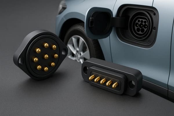
interface duty and qualification requirements rather than the presence
of magnets alone.
Application 5: IoT and Field Equipment — Make the Module Easier to Service
In distributed IoT systems, the economic problem is often different again.

The device may be installed in a location where opening the enclosure,
replacing the full unit or manually reconnecting a small plug is
inconvenient.

A magnetic interface can be useful when the product architecture allows:- field-replaceable sensor modules;
- temporary charging or programming connections;
- replaceable batteries or accessories;
- maintenance docks;
- modular product upgrades.
The key benefit is service boundary design
Engineers can deliberately decide which side of the interface should be
easier to replace.
For example:
    Installed Device
    ↓
    Controlled Magnetic Interface
    ↓
    Replaceable Sensor / Cable / Service Module


This can reduce the need to disturb the main device during routine service.
Outdoor does not automatically mean IP68 magnetic connector
The environmental boundary may include:- pogo pin feedthroughs;
- device housing;
- housing joint;
- gaskets;
- potting;
- cable entry;
- PCB or FPC termination.
A specific ingress-protection rating applies to a defined tested assembly,
not simply to the use of flat magnetic contacts.
The unmated state may be the real field condition
Serviceable IoT contacts can remain exposed when the accessory is removed.Engineers should consider:
- rain or condensation;
- dust;
- salt or industrial residue;
- metallic particles;
- foreign conductive objects;
- wet reconnection.
Environmental sealing and exposed-contact electrical safety should be
evaluated separately.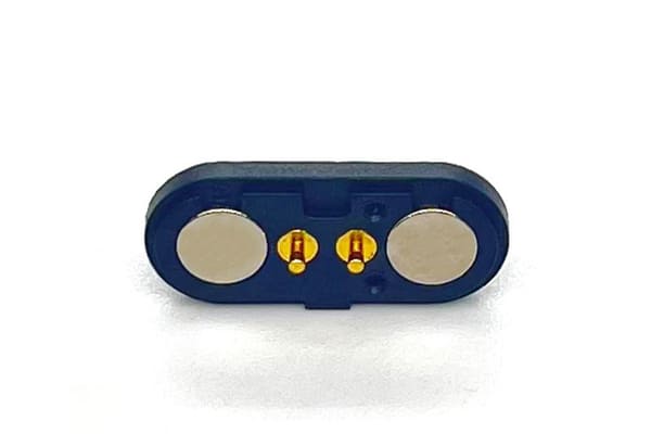
interface boundary, but exposed-state environmental risks still require
dedicated design controls.
Five Industries, Five Different Interface Duties
| Industry | Primary Interface Duty | Why Magnetic May Help | Main Engineering Control |
|---|---|---|---|
| Consumer Electronics | Frequent user mating | Reduces approach and alignment effort | Mechanical guidance and breakaway tuning |
| Medical Devices | Cleanable removable boundary | Can support a shallow external interface | Cleaning, materials and connection-state validation |
| Industrial Automation | Autonomous docking | Assists final capture without manual plugging | Docking tolerance, seating detection and contamination control |
| Automotive / Mobility | Controlled removable module | Can simplify specific service or docking interfaces | Dynamic, thermal and application-specific qualification |
| IoT / Field Equipment | Field serviceability | Supports replaceable modules or temporary service connections | Environmental boundary and unmated-state design |
The Same Magnetic Connector Benefit Means Different Things in Different Industries
This is the key design lesson.

“Easy mating” in a wearable is not the same requirement as “easy mating” in
an autonomous robot.

“Flat surface” in a medical instrument is not the same requirement as
“flat surface” in an outdoor sensor.

“High retention” in a user charging cable is not the same requirement as
retention in a vehicle-mounted module.

Engineers should therefore avoid selecting a magnetic connector from a
generic application label.
A better selection chain is:
    Industry
    ↓
    Actual Interface Duty
    ↓
    Mechanical Requirement
    ↓
    Electrical Requirement
    ↓
    Environmental State
    ↓
    Service Requirement
    ↓
    Magnetic Connector Architecture
Four Questions to Ask Before Choosing a Magnetic Connector
1. Why Must the Interface Be Removable?
If the connection is permanent and rarely serviced, a magnetic architecture
may create little additional value.
2. What Mechanical Function Should the Magnet Perform?
Define whether the magnet is intended to provide:- capture;
- retention;
- breakaway behavior;
- some combination of these.
Do not ask the magnet to replace controlled mechanical datums.3. What Happens Before Full Seating?
Partial mating should be reviewed when different contacts can engage at
different times.

Where required, connection detection, module identification or controlled
power enable can be part of the Pin Map.
4. What Is the Real Environmental State?
Define whether the connector is exposed:- while mated;
- while unmated;
- while partially mated;
- after cleaning;
- while wet or contaminated.
These states can create different mechanical and electrical risks.Magnetic Connector Applications Should Be Validated at System Level
The application should not be approved from one connector specification
alone.
Relevant validation may include:
| Requirement | Possible Validation |
|---|---|
| Working Stroke | Minimum, nominal and maximum tolerance-stack condition |
| Retention | Defined pull, peel or off-axis condition |
| Power | Complete-path voltage drop and temperature rise |
| Signals | Required channel performance under representative assembly conditions |
| Dynamic Load | Electrical continuity during defined vibration or shock |
| Environment | Defined mated or unmated exposure and post-test inspection |
| Lifecycle | Project-specific mating profile and end-of-life criteria |
| Contamination | Representative dust, residue or metallic debris where relevant |
When a Conventional Connector May Be the Better Choice
Magnetic connectors are not the best architecture for every application in
these five industries.
A conventional connector may be preferable when:
- positive mechanical locking is required;
- the connection remains permanent for most of the product life;
- standardized third-party interoperability is essential;
- very high contact density dominates the design;
- an established high-speed interface already meets the requirement;
- ferromagnetic contamination cannot be controlled;
- magnetic-sensitive components create unacceptable constraints;
- removable capture or breakaway provides little product-level value.
The correct architecture is the one that best satisfies the complete
product requirement—not the one with the most features.
Information Needed for a Custom Magnetic Connector Application Review
| Project Input | Information to Provide |
|---|---|
| Application | Which two assemblies need to connect? |
| Interface Duty | Charging, docking, removable module, service or another function |
| Mating Method | Manual, blind, automatic or fixture-controlled |
| Mechanical Envelope | Available X, Y and Z space |
| Mating Tolerance | X-Y-Z and angular variation |
| Working Stroke | Minimum, nominal and maximum compression |
| Pin Map | Power, return, detection, identification and signal functions |
| Electrical Load | Voltage, continuous current, peak current and duty cycle |
| Signal Requirement | Required control or communication channel |
| Magnetic Behavior | Capture, retention and separation requirements |
| Environment | Temperature, moisture, dust, sweat, salt, oil or chemicals |
| Lifecycle | Expected mating and service profile |
| Project Files | 2D drawing, 3D assembly, PCB layout or enclosure model |
Frequently Asked Questions
What are the main magnetic connector applications?
Common applications include wearable and portable charging interfaces,
removable medical modules, automated robot docking, selected automotive
modules and field-serviceable IoT equipment.
Why are magnetic connectors used in consumer electronics?
Their main value can be lower mating effort, blind or one-handed attachment,
shallow external geometry and controlled breakaway for frequently removable
interfaces.
Are magnetic connectors suitable for medical devices?
They can be suitable for selected removable or charging interfaces, but
cleanability, materials, exposed-contact behavior and application-specific
qualification must be evaluated separately.
Why are magnetic pogo pin connectors useful for robots?
Magnetic capture can assist the final stage of autonomous docking, while
mechanical guides and stops define final position and pogo pins provide
controlled electrical compliance.
Can magnetic connectors be used in automotive electronics?
They can be considered for selected removable, serviceable or docking
interfaces. They are not universal replacements for conventional
automotive connectors and still require location- and function-specific
validation.
Are magnetic connectors useful for IoT devices?
They can support field-replaceable modules, temporary charging, service or
programming interfaces where frequent access to the main enclosure is
undesirable.
Are magnetic connectors automatically waterproof?
No. Ingress protection depends on the complete connector and enclosure
boundary, including feedthroughs, housing joints, seals, potting and
terminations.
Do magnetic connectors supports reliable power during vibration?
No. Magnetic retention can help keep assemblies engaged, but electrical
continuity depends on working stroke, contact force, mechanical movement,
target geometry and the actual vibration condition.
Can magnetic connectors carry both power and data?
A custom Pin Map can support power, return, detection and selected signals,
but current and data capability must be validated from the complete
electrical path and channel architecture.
What is the most important factor when selecting a magnetic connector application?
Start with the interface duty: why the connection must be removable, how it
should mate, what must cross the electrical boundary, what environment it
will see and how the product will be serviced.
When should I avoid a magnetic connector?
Another architecture may be better when positive locking, permanent
connection, standardized interoperability, very high contact density or
unmanaged ferromagnetic contamination is the dominant requirement.
Request a Magnetic Connector Application Engineering Review
Explore

    CTP custom magnetic connector solutions

for removable charging, docking and modular product interfaces.

Review

    pogo pin and spring-contact connector solutions

for different contact structures and mounting architectures.

Learn more about CTP engineering and manufacturing capabilities on the

    About Us page
. Submit your interface duty, connector envelope, Pin Map, working stroke,
voltage, current, mating tolerance, magnetic behavior, environmental
conditions and available 2D or 3D files to CTP for an engineering review.
The goal is to determine whether magnetic capture creates meaningful
product-level value and how mechanical positioning, electrical contact,
environmental protection and service requirements should be divided
across the complete interface.
Final electrical performance, magnetic behavior, environmental
protection, lifecycle and dynamic stability should be confirmed against
the approved connector revision and project-specific validation
conditions.
CTP ENGINEERING PATHS
Choose the right path for your project
Move from application requirements to a connector pair, a data-capable cable assembly, or a charging cable configuration. Final specifications are confirmed against an approved drawing and project validation plan.
Magnetic Connectors
Connector geometry, pin layout, mechanical integration and OEM/ODM review.
Engineering overview → 02Magnetic Data Cables
Power and signal allocation, cable exit, interface selection and assembly review.
Cable engineering → 03Magnetic Charging Cables
Browse the complete cable catalog and shortlist a starting structure for customization.
View cable catalog →