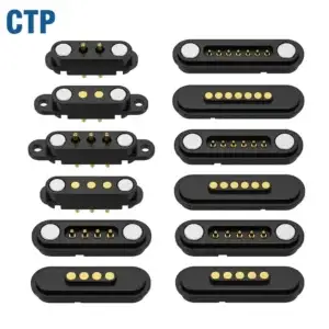
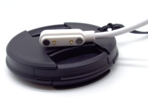
Designing a magnetic pogo pin connector for a harsh environment requires more than selecting a temperature range or requesting an IP rating. Engineers must define the actual exposure conditions, control the working stroke across temperature, manage condensation and contamination, evaluate the complete electrical path and validate the connector in its final enclosure.
A magnetic pogo pin connector does not become suitable for a harsh environment simply because it uses magnets, gold-plated contacts or a sealed housing. Environmental performance depends on the complete interface, including the pogo pin, mating pad, magnet, housing, adhesive, seal, PCB, cable termination and surrounding device structure.
High temperature, low temperature, temperature change, humidity, condensation, salt, dust and cleaning chemicals create different failure mechanisms. These conditions should be defined separately before materials, dimensions and validation methods are selected.
This guide explains how engineers can establish an environmental design envelope and apply practical derating rules to a custom magnetic pogo pin connector.
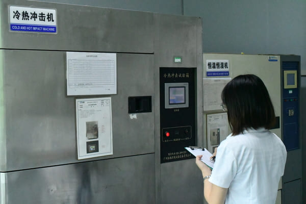
What Is a Harsh Environment for a Magnetic Pogo Pin Connector?
A harsh environment is any operating, storage or transportation condition that can alter the connector’s electrical contact, mechanical movement, material stability or enclosure protection.
Typical environmental stresses include:
- High or low operating temperature
- Rapid or repeated temperature changes
- High relative humidity
- Condensation on or inside the connector
- Rain, temporary immersion or water spray
- Salt, sweat or coastal atmosphere
- Dust, powder, fibers or metallic particles
- Oil, coolant or industrial chemicals
- Cleaning agents and disinfectants
- Vibration, cable movement and mechanical shock
- Outdoor ultraviolet exposure
- Storage and transportation outside the normal operating range
The phrase “harsh environment” should therefore be converted into measurable project requirements. A connector intended for a wearable device exposed to sweat requires a different design from an outdoor connector exposed to rain or an industrial connector exposed to oil and metal dust.
Start with an Environmental Design Envelope
Before selecting the connector structure, document the maximum and minimum conditions expected during use, storage, transportation and cleaning.
| Environmental Input | Engineering Question | Connector Design Impact |
|---|---|---|
| Operating temperature | At what temperature must the connector carry current or transmit signals? | Material selection, contact resistance, current derating and housing dimensions |
| Storage temperature | What temperature may occur while the device is unpowered? | Material stability, adhesive retention and permanent deformation |
| Temperature transition | How quickly does the product move between hot and cold conditions? | Thermal expansion, condensation and interface stress |
| Humidity | Is the exposure constant, cyclic or combined with changing temperature? | Insulation, corrosion, leakage paths and moisture absorption |
| Condensation | Can water form directly on the connector or PCB? | Drainage, venting, sealing and electrical isolation |
| Liquid exposure | Is the liquid water, sweat, detergent, oil or another chemical? | Seal material, coating, adhesive and plating compatibility |
| Particles | What particle size, material and concentration may reach the interface? | Contact geometry, wiping behavior, recess depth and cleanability |
| Mechanical environment | Will the cable vibrate, move or pull on the connector? | Working stroke, magnetic force, cable strain relief and wear pattern |
Do not replace unknown environmental inputs with a supplier’s standard test condition. Record them as open engineering questions until the device team defines the intended use.
High Temperature, Low Temperature and Temperature Change Are Different Problems
A connector can pass a steady high-temperature test and still fail during repeated hot-to-cold transitions. Engineers should distinguish between three conditions.
Steady High Temperature
High temperature can affect:
- Electrical resistance of the complete current path
- Temperature rise under load
- Spring-force stability
- Housing stiffness and dimensional stability
- Adhesive and overmolding retention
- Cable insulation and strain-relief materials
- Magnet coating and retention structure
IEC 60068-2-2:2025 provides dry-heat methods for heat-dissipating and non-heat-dissipating specimens. It can be applied to energized or non-energized specimens, but the project specification must define the operating state, temperature, exposure duration and acceptance criteria.
Steady Low Temperature
Low temperature can change:
- Housing and cable flexibility
- Seal compression
- Adhesive behavior
- Dimensional stack-up
- Plunger movement when moisture or contamination is present
- Mechanical response during impact or cable movement
IEC 60068-2-1:2025 addresses cold-temperature testing for components and equipment. A low-temperature storage result should not automatically be treated as proof of powered operation at the same temperature.
Temperature Change
Temperature change introduces differential expansion between materials. The pogo pin barrel, housing, PCB, mating pad, magnet and enclosure may not expand or contract at the same rate.
This can change:
- The installed working height
- The compression stroke
- The spring force
- The magnetic air gap
- The seal compression
- The position of the mating pad
- Stress on solder joints and cable terminations
IEC 60068-2-14:2023 provides test methods for analysing the effect of specified ambient-temperature changes. It should not be replaced by a simple high-temperature or low-temperature exposure because steady temperature and changing temperature address different risks.
Calculate Working Stroke Across the Temperature Range
The pogo pin working stroke should be checked at the minimum and maximum assembly conditions, not only at room temperature.
The tolerance analysis should include:
- Pogo pin free height
- Housing height
- PCB thickness and installed position
- Mating-pad position
- Seal compression
- Adhesive or overmolding thickness
- Thermal expansion of the mating halves
- Mechanical deflection under magnetic force
At every design limit, confirm that the pogo pin remains within the approved working-stroke window.
| Condition | Potential Risk | Engineering Review |
|---|---|---|
| Minimum compression | Insufficient contact force and intermittent connection | Check minimum spring force and dynamic continuity |
| Nominal compression | Normal electrical and mechanical operation | Use as the primary design point |
| Maximum compression | Excessive stress, wear or mechanical bottoming | Check available over-travel and housing load |
| Hot assembly condition | Reduced clearance or increased compression | Review thermal stack-up and material expansion |
| Cold assembly condition | Loss of compression or increased seal stiffness | Review minimum installed height and return movement |
Magnetic attraction cannot correct an incorrect working height. It may pull the two connector halves together, but the final pogo pin compression is still determined by the mechanical stack-up.
Electrical Current Must Be Derated for the Actual Environment
A current value should not be applied to every connector configuration without considering contact resistance, pin quantity, cable size, PCB copper, ambient temperature and duty cycle.
The complete current path may include:
- Pogo pin internal structure
- Mated contact interface
- Target pad
- PCB pad and solder joint
- Wire, crimp, weld or solder termination
- Cable and external connector
For high-temperature or enclosed applications, evaluate:
- Contact resistance by individual power channel
- Voltage drop across the complete interface
- Temperature rise after stabilization
- Current sharing between parallel contacts
- Effect of minimum working stroke
- Effect of contamination or surface ageing
- Heat transfer into the surrounding enclosure
A connector that carries the required current at room temperature in open air may require derating when installed inside a sealed enclosure or operated near another heat source.
Humidity and Condensation Must Be Treated Separately
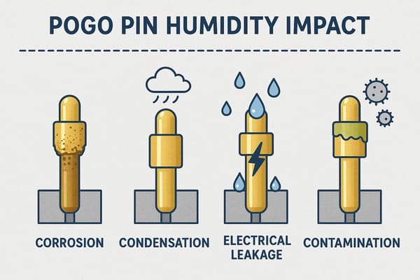
High relative humidity does not always mean that liquid water forms on the connector. Condensation occurs when a surface reaches conditions where moisture can deposit directly on it.
Condensation can create:
- Temporary leakage paths between contacts
- Corrosion at pores or worn surfaces
- Moisture migration along cables or housings
- Contamination concentration after evaporation
- Reduced insulation resistance
- Moisture retention inside recesses
IEC 60068-2-30:2025 addresses cyclic damp heat with changing temperature and conditions that generally produce condensation on the specimen. This is different from a steady-humidity exposure.
When condensation is possible, the design review should consider:
- Whether water can drain away from the contact area
- Whether enclosed cavities can vent and dry
- Whether the contact interface traps liquid
- Whether adjacent pins have sufficient creepage and clearance for the application
- Whether the PCB has exposed conductive paths
- Whether the connector is powered during condensation
- Whether contaminants remain after the moisture evaporates
Waterproofing Is an Enclosure-Level Requirement
An individual pogo pin does not independently create an IP-rated device. The final protection level depends on the assembled enclosure, including:
- Connector housing
- O-rings or gaskets
- Adhesive and potting
- Fasteners
- Cable entry
- PCB interface
- Mating condition
- Manufacturing tolerances
IEC 60529 classifies degrees of protection provided by electrical enclosures. Therefore, an IP claim should identify the exact enclosure, assembly state and test condition covered by the result.
The engineering specification should answer:
- Is the device protected while the connector is mated, unmated or both?
- Is the seal part of the removable cable or the device housing?
- Does repeated mating change seal compression?
- Must the enclosure remain protected after mechanical cycling?
- Can water collect behind the connector?
- Is pressure equalization or drainage required?
A magnetic connector can assist repeatable positioning, but magnetic attraction should not be described as the waterproofing mechanism.
Salt Mist Is Not the Same as Field-Life Prediction
Salt mist can be useful for comparing coating quality and identifying discontinuities, pores or defects in protective finishes.
It does not directly reproduce every real coastal, marine, wearable or industrial environment.
IEC 60068-2-11:2021 defines a salt-mist method for assessing corrosion resistance and the comparative quality and uniformity of protective coatings. It should not be converted into a universal statement such as “a certain number of test hours equals a certain number of years in the field.”
For corrosion-sensitive projects, review:
- Contact and mating-pad base materials
- Surface finish and barrier layers
- Magnet coating
- Adjacent dissimilar metals
- Drainage and moisture retention
- Wear through the contact finish
- Assembly contamination
- Cleaning residues
- Whether current flows while the interface is wet
Gold Plating Alone Does Not Solve Environmental Exposure
The performance of a contact finish depends on more than the presence of gold.
Engineers should specify and review:
- Base material
- Barrier layer
- Contact finish
- Finish thickness where required
- Surface roughness
- Contact-tip geometry
- Normal force
- Sliding or wiping distance
- Expected environmental contaminants
A hard, abrasive mating pad combined with excessive sliding may damage the finish. A low-force interface may be unable to penetrate light contamination. A high-force interface may accelerate wear.
The plating specification, spring force and mating motion should therefore be evaluated as one contact system.
Control Contamination at the Contact Interface
Dust and particles can affect a magnetic pogo pin connector differently depending on particle size, material and contact geometry.
Potential effects include:
- Blocking full pogo pin compression
- Increasing contact resistance
- Causing plunger sticking
- Creating conductive bridges between contacts
- Scratching the contact finish
- Accumulating around the magnets
Magnetic particles require special attention because they may be attracted to the connector face or magnet structure.
Possible design measures include:
- Reducing particle-trapping recesses
- Providing a cleanable contact surface
- Recessing or shielding sensitive contact areas
- Controlling the wiping path
- Separating magnets from exposed metallic debris where practical
- Providing drainage or escape paths
- Defining maintenance and cleaning instructions
Cleaning Chemicals Require Compatibility Review
Medical, laboratory, consumer and industrial devices may be cleaned with alcohol, detergent, disinfectant or process chemicals.
Chemical compatibility should be reviewed for:
- Housing resin
- Seal material
- Adhesive
- Overmolding
- Cable jacket
- Magnet coating
- Contact finish
- Printed markings
The project should define:
- Chemical name and concentration
- Application method
- Contact duration
- Cleaning frequency
- Drying process
- Whether the connector is powered during or after cleaning
“Chemical resistant” is not a complete specification without the chemical, concentration and exposure condition.
Magnet Design Must Include Temperature, Coating and Retention
Magnet selection should not be based only on the maximum initial pull force.
The complete magnetic system includes:
- Magnet material and grade
- Magnet dimensions
- Protective coating
- Retention method
- Housing around the magnet
- Assembled air gap
- Steel or magnetic return path
- Polarity arrangement
- Operating-temperature requirement
For a harsh-environment design, verify:
- Holding force across the temperature range
- Magnet position after temperature and humidity exposure
- Coating condition after environmental exposure
- Adhesive or mechanical retention
- Final air gap after enclosure deformation
- Capture and alignment with contamination present
Excessive magnetic force can also create design problems by increasing housing load, making cable release difficult or compressing the pogo pins beyond the intended stroke.
Separate Magnetic Holding Force from Contact Spring Force
Magnetic force and pogo pin spring force perform different functions.
| Force | Primary Function | Environmental Concern |
|---|---|---|
| Magnetic capture force | Brings the two connector halves together | Air gap, temperature, contamination and magnet position |
| Magnetic holding force | Maintains the mated condition | Cable pull, vibration and enclosure deformation |
| Pogo pin spring force | Creates electrical contact pressure | Working stroke, temperature and mechanical wear |
| Housing or seal reaction force | Maintains geometry and enclosure sealing | Material stiffness and compression set |
A connector can have adequate magnetic holding force while one pogo pin remains under-compressed. Each force should have its own requirement and measurement method.
Review the PCB, Cable and Enclosure as Part of the Connector
Harsh-environment failures frequently occur outside the discrete pogo pin.
The design review should include:
- PCB surface finish
- PCB support and flexing
- Solder-joint geometry
- Conformal coating boundaries
- Drainage around the PCB
- Cable conductor size
- Cable jacket compatibility
- Crimp, solder or weld termination
- Strain relief
- Overmolding and cable entry
- Housing venting
- Potential moisture migration along the cable
Testing only the removable connector head may miss device-level problems caused by the PCB, cable or enclosure.
Recommended Environmental Derating Review
Derating means operating the connector below a limiting condition to provide margin for production variation, ageing and environmental exposure.
| Parameter | Do Not Base It Only On | Review Before Approval |
|---|---|---|
| Current per contact | Room-temperature pin rating | Complete path, ambient temperature, duty cycle and enclosure |
| Working stroke | Nominal room-temperature dimension | Full tolerance and temperature stack-up |
| Magnetic holding force | Initial peak pull value | Direction, air gap, temperature and contamination |
| Water protection | Connector material or magnet type | Final enclosure, mating state and seal process |
| Corrosion resistance | Gold appearance or salt-mist duration alone | Material system, wear, contaminants and field exposure |
| Temperature range | One individual material specification | All materials, adhesives, cables, magnets and assembled function |
Match the Test Method to the Environmental Risk
The following standards may provide test-method references. They do not define a universal severity or acceptance limit for every magnetic connector.
| Environmental Risk | Possible Reference | What It Helps Evaluate |
|---|---|---|
| Low temperature | IEC 60068-2-1:2025 | Use, transportation or storage at low temperature |
| High temperature | IEC 60068-2-2:2025 | Use, transportation or storage at high temperature |
| Temperature changes | IEC 60068-2-14:2023 | Effects of specified ambient-temperature changes |
| Cyclic humidity and condensation | IEC 60068-2-30:2025 | High humidity combined with cyclic temperature changes |
| Salt mist | IEC 60068-2-11:2021 | Comparative corrosion resistance and coating quality |
| Enclosure ingress protection | IEC 60529 | Degree of protection provided by the assembled enclosure |
For each selected test, define:
- Connector and device configuration
- Mated or unmated state
- Powered or unpowered state
- Electrical load
- Temperature or environmental severity
- Exposure duration
- Recovery period
- Pre-test and post-test measurements
- Pass and failure criteria
Environmental Design Review Checklist
Before prototype release, confirm the following questions.
Temperature
- Are operating, storage and transportation temperatures defined separately?
- Has the working stroke been calculated at the temperature limits?
- Has current been evaluated at the highest operating temperature?
- Have all housing, seal, adhesive, cable and magnet materials been reviewed?
Humidity and Liquids
- Can condensation occur inside the device?
- Can liquid drain and the enclosure dry?
- Is the connector protected when mated, unmated or both?
- Are cleaning chemicals and exposure frequencies defined?
Contact Interface
- Are contact force and working stroke defined?
- Is the surface finish compatible with the mating pad?
- Can particles become trapped between the contacts?
- Will sliding or lateral movement damage the finish?
Magnetic Structure
- Are holding force and breakaway force measured in the intended directions?
- Has the assembled air gap been controlled?
- Is magnet retention suitable for temperature and humidity exposure?
- Can magnetic particles collect on the connector face?
System Integration
- Are the PCB, cable and solder joints included in the validation?
- Is cable strain transferred into the connector?
- Does enclosure deformation change pogo pin compression?
- Can moisture migrate through the cable entry?
Engineering Reference Standards
The applicable edition, test severity and acceptance criteria should be confirmed in the project specification.
- IEC 60068-2-1:2025 — Cold testing
- IEC 60068-2-2:2025 — Dry heat testing
- IEC 60068-2-14:2023 — Change of temperature
- IEC 60068-2-30:2025 — Cyclic damp heat
- IEC 60068-2-11:2021 — Salt mist
- IEC 60529 — Degrees of protection provided by enclosures
Frequently Asked Questions
Does a magnetic connector automatically perform better in harsh environments?
No. Magnetic attraction can assist mating and retention, but environmental performance still depends on working stroke, materials, sealing, contact geometry, cable design and the final enclosure.
Can one temperature rating be applied to the complete connector?
Only after every critical material and function has been reviewed. The housing, spring, magnet, adhesive, seal, cable and electrical path may have different limitations.
Does IP68 mean that the pogo pins cannot corrode?
No. An IP rating describes enclosure protection under defined conditions. It does not independently prove contact-surface corrosion resistance, cycle life or chemical compatibility.
Is salt-mist testing a prediction of outdoor service life?
No. Salt-mist testing can compare corrosion resistance and coating quality, but it should not be directly converted into a universal number of field years.
Should the connector be powered during environmental testing?
That depends on actual use and the suspected risk. Powered and unpowered exposure can produce different electrical, thermal and corrosion conditions.
Why can a connector pass at room temperature but fail in the device?
The final device may introduce higher ambient temperature, tolerance stack-up, enclosure deformation, cable loading, condensation or reduced heat dissipation that is not present during a room-temperature component test.
Does stronger magnetic force improve environmental reliability?
Not necessarily. Higher magnetic force may improve holding strength, but it can also increase housing load, make breakaway difficult or create excessive pogo pin compression.
Prepare the Environmental Inputs for a Custom Connector Review
Provide the following information before selecting or modifying a magnetic pogo pin connector:
- Application and device type
- Operating, storage and transportation temperatures
- Temperature-change rate or use scenario
- Humidity and condensation conditions
- Water, sweat, oil or chemical exposure
- Dust or particle conditions
- Voltage, current and duty cycle
- Pin map and contact function
- Working height and tolerance stack-up
- Magnetic holding and breakaway requirements
- PCB, cable and housing drawings
- Required enclosure-protection level
- Available validation specifications
Review available custom magnetic connector structures, access additional connector engineering guides, or submit your drawings and environmental requirements through the Get Quote & Samples page.
CTP can review the electrical path, connector geometry, working stroke, magnetic structure, materials and environmental inputs before prototype development. Final operating limits, test conditions and acceptance criteria should be confirmed in the approved drawing and project specification.
CTP ENGINEERING PATHS
Choose the right path for your project
Move from application requirements to a connector pair, a data-capable cable assembly, or a charging cable configuration. Final specifications are confirmed against an approved drawing and project validation plan.
Magnetic Connectors
Connector geometry, pin layout, mechanical integration and OEM/ODM review.
Engineering overview → 02Magnetic Data Cables
Power and signal allocation, cable exit, interface selection and assembly review.
Cable engineering → 03Magnetic Charging Cables
Browse the complete cable catalog and shortlist a starting structure for customization.
View cable catalog →