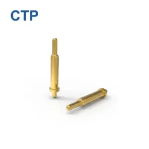
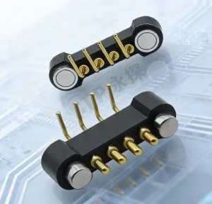
A pogo pin manufacturer should not receive only a diameter, overall height and current target. A production-ready spring-loaded contact is defined by the complete product interface: how the pin is mounted, where the mating target sits, how much the pin is compressed after assembly, what force window is required, how current enters and leaves the contact, and which conditions the finished product must survive.
This is why a custom pogo pin project should be treated as an engineering transfer rather than a part-number request.
The development sequence should connect:
Product Requirement → Interface Definition → Manufacturer Drawing → Prototype → Validation → Pilot Build → Production Control.
A sample that fits and conducts electricity is useful, but sample approval is not automatically production approval.
What Should a Pogo Pin Manufacturer Actually Receive from the OEM?
A manufacturer can only control requirements that have been translated into measurable engineering inputs.
At the beginning of a project, the OEM may know only that the device needs a spring-loaded contact. That is enough to start a discussion, but not enough to freeze the part.
The first engineering package should progressively clarify:
- what electrical function the contact performs;
- how the two product halves mate;
- available X, Y and Z space;
- free and installed contact geometry;
- expected compression range;
- mating-target geometry;
- PCB, wire, FPC or other termination;
- continuous and peak electrical conditions where relevant;
- expected mating or operating duty;
- environmental exposure;
- prototype and production requirements.
Not every value has to be finalized before the first discussion. The important point is to identify which variables are known, which are assumptions, and which require joint engineering review.
Start with the Product Interface, Not a Catalog Pogo Pin
A pogo pin is one element inside a larger mechanical and electrical system.
The product may use a single pin, a multi-contact housing, a battery interface, a board-to-board structure, a charging dock, a test fixture, or another removable contact architecture.
Before selecting the pin itself, define the interface duty.
| Requirement Area | Engineering Question |
|---|---|
| Electrical function | Power, return, signal, detection, sensing, programming or another function? |
| Contact state | Continuously compressed, repeatedly mated, or used only during testing? |
| Mechanical package | What space, approach direction and final seating geometry are available? |
| Mounting | PCB, wire, FPC, solder cup, press-fit structure or connector module? |
| Mating target | What surface does the plunger actually contact? |
| Environment | What temperature, moisture, contamination, vibration or cleaning conditions are relevant? |
| Lifecycle | How often will the contact be compressed, mated, removed or serviced? |
This prevents a common sourcing mistake:
Catalog part selected first → product stack-up adapted around it → insufficient working-stroke or mounting margin discovered later.
The better sequence is:
Product interface → installed geometry → contact requirement → pogo pin structure.
Separate Free Height, Working Height and Total Travel
One of the most important discussions with a pogo pin manufacturer is the installed compression condition.
Three dimensions should not be treated as interchangeable:
- Free height: the contact height before the product compresses the plunger;
- Working height: the installed height in the intended operating condition;
- Total travel: the available mechanical movement before the contact reaches its travel limit.
The installed compression can be represented conceptually as:
Installed compression = free contact height − seated contact height
The seated contact height is created by the finished product stack-up rather than by the pogo pin alone.
Possible contributors include:
- PCB position;
- connector mounting height;
- housing dimensions;
- target position;
- mechanical-stop geometry;
- solder or mounting variation;
- assembly tolerance;
- structural deflection.
Therefore, an OEM should avoid sending a drawing that defines only total pin length while leaving the real installed compression undefined.
A manufacturer-ready drawing should support evaluation of minimum, nominal and maximum installed conditions.
Define the Mating Target Together with the Pogo Pin
The opposite contact surface is part of the electrical interface.
A pogo pin cannot be fully specified without understanding where and how the plunger will make contact.
The mating target affects:
- installed working stroke;
- contact location;
- tip geometry selection;
- target overlap;
- wear behavior;
- contact resistance stability;
- alignment tolerance;
- cleaning or contamination sensitivity.
This creates an important design rule:
Do not qualify the pogo pin while treating the mating target as an unrelated PCB detail.
The contact and target should be reviewed as one interface.
If the target position can move significantly because of PCB, enclosure or assembly tolerance, that variation should enter the working-stroke analysis before the manufacturer drawing is frozen.
Select Mounting and Termination from the Product Assembly
The same contact concept can require very different structures depending on how it is installed.
Possible architectures include surface-mount, through-hole, right-angle, double-ended, wire-terminated, press-fit or custom module structures.
The mounting decision should follow the complete product assembly process.
| Question | Why It Matters |
|---|---|
| How is the contact located before soldering or assembly? | Defines placement and positional-control requirements |
| What process attaches it to the PCB or conductor? | Affects termination geometry and manufacturing compatibility |
| What external mating load reaches the PCB? | Determines whether additional mechanical support is required |
| Does the contact need to face vertically or horizontally? | Influences package and termination architecture |
| Will the pin be assembled individually or inside a housing? | Changes alignment, inspection and production strategy |
The pogo pin should not be expected to act as the structural support for loads that should be carried by the product housing or connector body.
Likewise, the termination should be reviewed as part of the complete electrical path rather than as a separate manufacturing detail.
Translate Electrical Requirements into Testable Conditions
An RFQ that says only “high current” or “low resistance” is incomplete.
The manufacturer needs a defined operating condition.
Useful electrical inputs can include:
- system voltage;
- continuous current;
- peak current, duration and repetition where relevant;
- power, return, signal or detection function;
- allowable system voltage drop;
- PCB, wire or FPC termination structure;
- ambient and duty conditions;
- required post-test electrical checks.
For a power contact, the complete current path may include:
Source → PCB or wire → termination → pogo contact → mating interface → target → device conductor → load → return path
This matters because current capability cannot be inferred from the pogo pin alone.
The basic electrical relationships are:
Vdrop = I × Rpath
Ploss = I² × Rpath
The manufacturer may control the spring-loaded contact, but the OEM still controls important parts of the finished path such as PCB copper, cable structure, target geometry and system thermal conditions.
The specification should therefore separate:
component requirement from complete system requirement.
Turn the Engineering Design into a Controlled Manufacturer Drawing
The development process becomes more robust when assumptions are converted into drawing-controlled requirements.
A useful manufacturer drawing can define the dimensions and characteristics that determine fit and function without trying to turn every dimension into a critical requirement.
Depending on the project, important drawing items may include:
- overall envelope;
- barrel and plunger dimensions;
- free height;
- working-height reference;
- approved compression range;
- termination geometry;
- tip geometry;
- mounting datum;
- material and finish requirements where approved;
- force checkpoints where required;
- electrical test condition;
- inspection references;
- revision identification.
Not Every Dimension Is a CTQ
CTQ means a characteristic that is critical to the intended quality or function of the product.
If every drawing dimension is treated as equally critical, inspection becomes expensive without necessarily improving interface control.
If true functional dimensions are not identified, production can meet the drawing while still creating a poor assembled condition.
The engineering team should therefore ask:
Which dimensions or characteristics directly control fit, working stroke, force, electrical contact, mounting or mating alignment?
Those characteristics deserve the strongest production attention.
What Should the First Prototype Sample Actually Prove?
The first custom sample should answer engineering questions rather than simply demonstrate that the manufacturer can produce the geometry.
A useful prototype review can include:
- dimensional fit in the actual product or representative fixture;
- minimum, nominal and maximum installed compression where practical;
- mating-target contact location;
- spring behavior at the intended stroke;
- electrical continuity or resistance under the defined test condition;
- termination compatibility;
- assembly-process compatibility;
- alignment and side-load behavior;
- visible damage or abnormal wear after representative operation.
The prototype is especially valuable for exposing incorrect assumptions in the OEM stack-up.
For example:
Nominal sample fits → final enclosure adds tolerance → actual working stroke changes → production design no longer matches the prototype condition.
This is why prototype validation should use the complete interface wherever possible.
Why Sample Approval Is Not Production Approval
A prototype can be hand-selected, hand-assembled and carefully adjusted.
Mass production introduces distributions.
Variation can come from:
- machined component dimensions;
- spring characteristics;
- plating and surface processing;
- assembly position;
- housing dimensions;
- PCB assembly;
- target flatness;
- inspection method;
- production fixtures;
- supplier process changes.
Therefore:
Prototype fit → prototype validation → pilot-process validation → production release
should be treated as separate stages.
The engineering question changes at each stage.
| Stage | Main Question |
|---|---|
| Engineering sample | Does the contact concept work? |
| Prototype | Does the contact work in the intended product architecture? |
| Validation build | Does it remain inside the approved mechanical and electrical window? |
| Pilot production | Can the manufacturing process reproduce the approved condition? |
| Mass production | Can CTQs and process changes remain controlled over time? |
Define CTQs Before the Pilot Build
The pilot phase should connect the approved engineering design to repeatable manufacturing control.
Useful CTQs depend on the actual design, but they may involve:
- critical installed height;
- working-stroke-related dimensions;
- plunger or barrel geometry;
- termination dimensions;
- spring-force checkpoints;
- contact resistance under a defined measurement condition;
- surface or plating requirements from the approved drawing;
- housing position for connector assemblies;
- mating-target geometry where supplied as part of the assembly.
The important rule is:
Inspection should control the characteristics that protect the engineering function.
A large inspection report is not automatically useful if it does not cover the dimensions that determine the installed contact condition.
Control Engineering Changes After Validation
A pogo pin can look identical after an internal manufacturing change while its functional behavior changes.
Depending on the design, changes that may require engineering review include:
- spring specification;
- contact material;
- surface or plating system;
- critical machining tolerance;
- plunger-tip geometry;
- assembly process;
- termination structure;
- tooling or fixture affecting a CTQ;
- manufacturing location where the approved process is not equivalent.
This does not mean every production adjustment requires full product requalification.
It means the OEM and manufacturer should define a change-control path that distinguishes:
process adjustment → controlled manufacturing change → engineering-impacting design change.
Where a change can affect fit, working stroke, force, electrical performance, durability or the mating interface, the required review and revalidation scope should be defined before implementation.
Common OEM-to-Manufacturer Handoff Failures
| Handoff Failure | Why It Creates Risk | Better Engineering Input |
|---|---|---|
| Only overall pin dimensions are supplied | Installed working condition remains undefined | Provide free and seated geometry plus stack-up |
| Total travel is used as working stroke | Production design may operate near a mechanical limit | Define an approved installed compression window |
| Mating target is not reviewed | Tip, overlap and alignment may not match the real interface | Include target geometry and position |
| Current target is provided without duty or environment | Electrical and thermal condition is ambiguous | Define continuous/peak load and test condition |
| Prototype sample becomes the only specification | Production variation has no controlled engineering reference | Freeze an approved drawing and CTQs |
| Every dimension becomes a CTQ | Inspection cost increases without focusing on functional risk | Identify dimensions that directly protect fit and function |
| Production change is evaluated only by appearance | Internal functional behavior can change without visible geometry change | Use revision and change-control review |
| OEM validates the pin but not the final interface | PCB, target, housing and stack-up problems remain hidden | Validate representative assembled conditions |
When an Off-the-Shelf Pogo Pin Is the Better Choice
Custom manufacturing is not automatically the best engineering decision.
An existing catalog contact may be preferable when:
- the available product already fits the required installed geometry;
- the mounting and target arrangement are compatible;
- the electrical and environmental conditions can be validated without modification;
- prototype and production quantities do not justify a new structure;
- standardization and second-source availability are more important than package optimization;
- custom tooling or qualification would add cost without creating meaningful product value.
Customization is most useful when a real interface constraint cannot be solved cleanly by a standard contact.
The correct question is therefore not:
“Can the manufacturer customize this pogo pin?”
It is:
“Which project constraint requires customization, and how will the customized feature be controlled and validated?”
What to Send a Pogo Pin Manufacturer for Engineering Review
A useful project package does not need to be perfect before the first engineering discussion.
Provide the information that already exists and clearly identify what still needs confirmation.
Useful inputs include:
- application and contact function;
- available X, Y and Z space;
- free and installed height targets;
- mechanical stop and mating direction;
- mating target drawing or geometry;
- expected tolerance or alignment range;
- PCB, FPC, wire or other termination;
- system voltage;
- continuous and peak current where applicable;
- signal or detection requirements;
- environmental exposure;
- expected operating or mating duty;
- prototype quantity and expected production volume;
- available 2D or 3D drawings;
- validation requirements already defined by the project.
Engineers who are still defining the contact itself can continue with the pogo pin design guide.
If the objective is to evaluate whether a shortlisted supplier has sufficient engineering and production evidence, continue with the pogo pin manufacturer audit guide.
Available pogo pin structures can be reviewed in the custom pogo pin product category.
Frequently Asked Questions
What does a pogo pin manufacturer need to quote a custom part?
A preliminary quote may begin with limited information, but a meaningful engineering review is easier when the OEM provides the application, available space, free and installed height, required working stroke, mounting method, mating target, electrical conditions, environment, quantity and available drawings.
Should I send the manufacturer a finished pogo pin drawing?
Not necessarily. If the contact has not yet been engineered, it can be better to provide the product interface and constraints first. The manufacturer can then evaluate whether an existing part, modified part or custom structure is appropriate.
What is the difference between a pogo pin sample and a production-approved pogo pin?
A sample proves a specific physical build can be made and tested. Production approval additionally requires controlled drawings, defined CTQs, representative validation and evidence that the manufacturing process can reproduce the approved condition.
Which pogo pin dimensions are most important?
The answer depends on the interface. Dimensions related to free height, installed working height, mounting, target position, plunger geometry and termination often affect function, but the actual CTQs should be defined from the product architecture rather than from a generic list.
Can a manufacturer choose the spring force for me?
A manufacturer can help optimize the spring design, but the OEM should define the system requirement that the force must satisfy. Total contact reaction, target durability, product stack-up and mating behavior all influence the acceptable force window.
Can current rating be specified from the pogo pin alone?
Not reliably for the finished product. The complete current path includes the pogo pin, mating interface, target, terminations, PCB or cable and return path. Current capability should be validated under defined assembly, duty and thermal conditions.
Should the mating pad be included in the manufacturer review?
Yes where it affects the interface. Target geometry, position, surface condition and alignment can influence working stroke, tip contact, wear and electrical stability.
What should be checked during the first prototype build?
Check real product fit, installed compression, target alignment, contact behavior, electrical condition, termination compatibility and any relevant movement or assembly effects before freezing the drawing.
When should CTQs be defined?
CTQs should be identified before pilot production so the manufacturing and inspection plan protects the characteristics that actually control fit and function.
How should engineering changes be handled after production approval?
The OEM and manufacturer should use an agreed change-control process. Changes that can affect working stroke, force, materials, plating, electrical performance, termination, critical tolerances or the mating interface should receive an engineering-impact review and the required level of revalidation.
Engineering Reference Sources
Request a Pogo Pin Engineering Review
If your project requires a custom spring-loaded contact, send the available interface drawing, free and installed height, mating target, mounting method, electrical condition, environment and expected production quantity. Missing parameters can be identified during the engineering review rather than guessed.