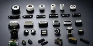
A drone magnetic pogo pin connector can simplify the electrical interface between a UAV and a removable payload, battery module, charging dock or field-service accessory. Spring-loaded contacts compensate for small dimensional variation, while magnets can assist alignment and hold the two mating surfaces together.
However, magnetic attraction should not automatically be treated as a replacement for every locking connector inside an aircraft. The correct architecture depends on whether the interface is connected only on the ground, repeatedly exchanged between missions or expected to remain secure throughout flight.
A magnetic breakaway connector may be useful for charging docks and removable accessories. A flight-critical power or control connection may require independent mechanical retention, redundancy and system-level safety analysis. Magnets should not be assumed to provide sufficient retention under every vibration, acceleration and impact condition.
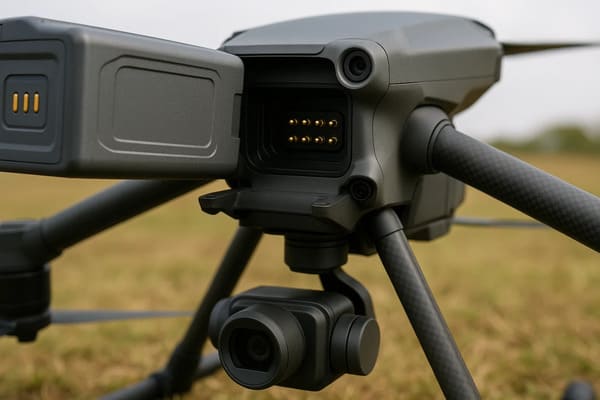
Where Magnetic Pogo Pin Connectors Fit in a Drone System
The term “drone connector” can describe several interfaces with very different reliability requirements. Before selecting the connector, engineers should define exactly where it will be installed and whether it remains connected during flight.
| UAV interface | Typical function | Primary design concern |
|---|---|---|
| Automatic charging dock | Ground charging after landing. | Landing tolerance, contact sequencing, drainage and charging current. |
| Removable payload module | Camera, sensor, spotlight or communication module. | Flight retention, vibration, pin allocation and module identification. |
| Battery service interface | Battery detection, charging or maintenance connection. | Current path, contact sequencing and prevention of accidental energization. |
| Programming and diagnostics | Firmware loading, testing and production inspection. | Repeatable alignment, signal allocation and fixture life. |
| Flight-critical internal connection | Power, propulsion control or essential flight data. | Positive retention, redundancy, vibration monitoring and fault containment. |
This distinction matters because a connector designed to detach safely from a charging dock may be unsuitable for a payload that must remain attached during maneuvering.
Three UAV Connector Architectures
1. Ground-only magnetic docking interface
A charging pad or maintenance fixture can use magnets to guide the drone into position after landing. The connector is not required to remain mated during flight, so controlled separation is usually desirable.
Typical design priorities include:
- large landing and positional tolerance;
- self-centering guide geometry;
- drainage and outdoor contamination control;
- ground or detection contact before main charging power;
- charging enable only after correct docking is confirmed;
- easy release during takeoff.
2. Magnetically aligned module with mechanical retention
For removable cameras, sensors or communication modules, magnets can simplify alignment while a latch, screw, rail or enclosure feature carries the flight load.
In this architecture:
- magnets assist assembly;
- mechanical features prevent separation during flight;
- pogo pins provide the electrical path;
- locating features control the final contact position.
This separation of functions is often safer than asking the magnetic system to provide alignment, electrical compression and flight retention at the same time.
3. Magnetic breakaway accessory
A magnetic breakaway interface may be appropriate for a ground accessory, temporary programming cable or device that should separate under excessive cable load.
It should be used cautiously for modules carried during flight. The required release force must be compared with expected acceleration, aerodynamic force, vibration and landing shock.
Do Not Let the Pogo Pins Carry the Structural Load
The pogo pins should provide axial contact force and electrical continuity. They should not be used as locating posts or structural supports for a heavy payload module.
A reliable UAV module interface may include:
- guide rails that carry shear load;
- locating pins that control radial position;
- housing shoulders that carry compression;
- a latch or fastener that prevents separation;
- pogo pins that move only along their intended axis.
Without this separation, side loads can cause plunger wear, tilted compression, uneven contact force or damage to the plastic housing.
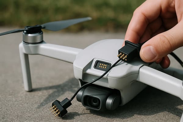
Working Compression Must Remain Stable During Flight
A pogo pin produces contact force only while it remains within its intended working-stroke range. The assembled UAV structure must maintain that compression despite manufacturing tolerance, frame deflection, temperature change and vibration.
The tolerance analysis should include:
- pogo pin installed height;
- module and airframe dimensions;
- PCB position;
- mating-pad height;
- guide and latch clearance;
- plastic or composite deformation;
- thermal expansion;
- wear after repeated module changes.
If compression becomes too low, contact resistance may become unstable. If compression becomes too high, the pogo pin may bottom out or transmit excessive force into the PCB and housing.
Check the complete array, not only one pin
In a multi-pin connector, housing tilt or flatness variation can create different compression values across the array. Engineers should measure the minimum and maximum working position of every contact, especially when the connector spans a wide payload interface.
Use Electrical Sequencing to Prevent Unsafe Partial Contact
During docking or module installation, all contacts may not engage at exactly the same moment. A tilted approach can cause one edge of the connector to touch first.
This matters when the interface contains battery power, digital signals and module-detection circuits.
Possible sequencing strategies include:
- ground contacts that engage before power;
- a dedicated module-detection pin;
- shorter detection contacts or longer ground contacts;
- software confirmation before enabling the main power rail;
- current limiting during initial connection;
- pre-charge for capacitive loads;
- power contacts positioned away from exposed edges.
The drone detects the module through a low-energy identification contact, verifies the expected accessory and then enables the main power output. This reduces the consequence of partial or incorrect contact.
Design the Pin Map for Fault Containment
A UAV connector should be reviewed not only in the correct position, but also under offset and partial-mating conditions.
Engineers should examine:
- one-pin offset in each direction;
- reversed module orientation;
- angular contact;
- one-side contact before full latching;
- conductive debris between adjacent pads;
- mating with the wrong accessory;
- loss of one ground or power contact.
Potential safeguards include:
- separating power contacts from sensitive signals;
- placing ground contacts around high-risk circuits;
- using asymmetric pin arrangements;
- adding mechanical keys;
- using accessory identification;
- limiting current until correct mating is confirmed.
Flight-Critical Circuits May Require Redundant Contacts
Where permitted by the system architecture, selected power, ground or detection functions may use more than one contact. Redundancy can reduce dependence on a single pogo pin, but simply connecting pins in parallel does not ensure equal performance.
Differences in the following can create unequal current or contact behavior:
- working compression;
- contact resistance;
- PCB trace length;
- solder-joint quality;
- pad condition;
- contamination.
Parallel contacts should be positioned and routed symmetrically where possible. Their current sharing and fault behavior should be measured in the assembled module.
Vibration Testing Must Monitor Electrical Continuity in Real Time
A connector can appear normal before and after a vibration test while still experiencing short interruptions during the test. For UAV electronics, dynamic monitoring provides more useful information than static resistance measurements alone.
A vibration evaluation may monitor:
- temporary open circuits;
- contact-resistance variation;
- module movement relative to the frame;
- latch or fastener movement;
- changes in pogo pin compression;
- damage to pads, plungers or housings.
The test setup should reproduce the actual module mass, mounting orientation and cable load. Testing a connector alone on a rigid fixture may not represent the behavior of the complete drone assembly.
Test more than one direction
Propulsion and airframe vibration can reach the connector through different axes. A design that performs well under axial vibration may behave differently under lateral or torsional movement.
Charging Dock Alignment Requires More Than Strong Magnets
Automatic docking introduces a different problem: the drone may land with positional, angular and height variation.
A charging interface may require:
- a funnel-shaped landing guide;
- compliant or floating contact mounts;
- large mating pads;
- controlled pogo pin stroke;
- magnets that complete final alignment;
- a contact surface that can drain water;
- charging detection before power is applied.
Magnets cannot correct unlimited landing error. The mechanical dock should bring the drone into a defined capture area before magnetic attraction and pogo pin compression become active.
Current Rating Depends on the Complete Charging Path
For a UAV charging dock or removable battery module, the current path may include:
- dock-side wiring;
- PCB traces or busbars;
- pogo pin components;
- mating pads;
- drone-side PCB copper;
- protection and charging circuitry.
The connector should be evaluated through voltage-drop and temperature-rise testing at the required continuous load. Pin diameter alone is not enough to determine the usable current.
Tests should consider:
- minimum expected compression;
- maximum ambient temperature;
- contact resistance after repeated docking;
- surface contamination;
- unequal current sharing between parallel contacts;
- heat trapped inside the drone or charging enclosure.
Data Connections Need a Defined Return Path
A multi-pin drone magnetic pogo pin connector may carry identification, control, serial communication or selected data signals. Higher data rates require more attention to the contact arrangement and PCB transition.
Review:
- signal and ground placement;
- return-path continuity;
- pin-to-pin coupling;
- PCB trace geometry;
- cable construction;
- shield termination;
- transition between the pogo pins and the customer PCB.
A metal housing may contribute to shielding, but it does not automatically provide complete EMI protection. The enclosure, grounding and cable structure must be evaluated together.
Metallic Debris Is a Specific Drone Maintenance Risk
Magnets can attract iron-containing particles from workshops, launch sites, vehicle decks and field-maintenance environments.
Debris around the connector may:
- bridge adjacent contacts;
- prevent full pogo pin compression;
- scratch the contact plating;
- increase the magnetic gap;
- create intermittent charging;
- interfere with module installation.
Possible controls include:
- recessed power contacts;
- insulating barriers between pads;
- protective covers when the interface is unused;
- drainage and cleaning access;
- maintenance inspection instructions;
- fault detection before enabling power.
Environmental Protection Must Be Designed at Module Level
A magnetic pogo pin connector can support a sealed UAV module, but the contacts and magnets alone do not establish a specific ingress-protection rating.
The complete design may need to address:
- water paths around the connector housing;
- PCB sealing;
- potting or insert molding;
- gasket compression;
- cable-entry sealing;
- condensation;
- salt or chemical exposure;
- drainage after landing outdoors.
Any waterproof or environmental rating should be based on testing of the assembled connector or UAV module under defined conditions.
UAV Connector Validation Matrix
| Validation area | Recommended evaluation |
|---|---|
| Alignment | Correct docking, offset approach, angular mating and wrong accessory mating. |
| Mechanical retention | Axial separation, shear load, module mass, latch performance and landing shock. |
| Electrical continuity | Real-time interruption and resistance variation during vibration. |
| Power path | Voltage drop, temperature rise, inrush current and parallel-contact sharing. |
| Sequencing | Ground, detection and main power engagement during partial mating. |
| Durability | Repeated module replacement or charging-dock cycles followed by electrical inspection. |
| Contamination | Dust, metallic particles, moisture and realistic cleaning procedures. |
| Environmental exposure | Temperature, humidity, corrosion and outdoor docking conditions. |
When a Magnetic Pogo Pin Connector May Not Be Suitable
A different connector architecture may be more appropriate when:
- the interface must remain locked under substantial flight loads;
- a standardized aerospace or industrial connector is mandatory;
- the contact face cannot be protected from conductive debris;
- the application requires high-speed data without custom signal validation;
- there is not enough space for magnets, guides and suitable contact spacing;
- the module remains permanently installed and does not need repeated mating;
- the system cannot tolerate any possibility of breakaway.
In these cases, a mechanically latched, threaded, board-to-board or wire-to-board connector may provide a clearer retention path.
Information Required for a Drone Connector Project
To evaluate a custom UAV connector, provide:
- whether the connector remains mated during flight;
- module type, mass and mounting position;
- pin count and pin assignment;
- continuous and peak current;
- signal type and required data rate;
- available connector dimensions;
- mating direction and allowable misalignment;
- retention or breakaway requirement;
- mechanical latch or guide concept;
- expected vibration and landing conditions;
- working temperature and outdoor exposure;
- charging-dock or hot-plug requirement;
- mating-cycle target;
- PCB, FPC, wire or cable termination;
- 2D drawings, 3D models and UAV enclosure references.
Frequently Asked Questions
Can a magnetic pogo pin connector power a drone during flight?
It may be technically possible in a properly designed system, but magnetic retention alone should not be assumed sufficient for a flight-critical power connection. Mechanical retention, redundancy, vibration performance and system fault response must be evaluated.
Are drone magnetic connectors mainly used for charging?
No. They can also support removable sensor modules, programming interfaces, maintenance fixtures and selected power or signal connections. The architecture should match the function and flight-retention requirement.
Can magnets automatically correct every landing misalignment?
No. A charging dock should first guide the drone into a defined capture area. Magnets can assist the final alignment but cannot compensate for unlimited horizontal, vertical or angular error.
How can a payload module be prevented from disconnecting during flight?
Use a mechanical latch, rail, fastener or enclosure feature to carry flight loads. Magnets can assist positioning, while the pogo pins provide electrical contact.
Can multiple pogo pins be used for higher charging current?
Yes, but equal current sharing should be verified through layout, resistance and temperature testing. Parallel contacts may not share current evenly when their compression or routing differs.
Can the connector be waterproof?
It can be integrated into a sealed module or docking structure. The final protection level depends on the complete housing, PCB, gasket, molding, drainage and cable-entry design.
How should vibration performance be tested?
Test the assembled module in realistic mounting orientations while continuously monitoring electrical continuity or resistance. Connector-only testing may miss movement caused by the payload, airframe or latch.
Conclusion
A drone magnetic pogo pin connector can simplify modular payload exchange, automated charging and field-service access. Its success depends on assigning clear functions to each part of the interface.
The housing and retention system should carry mechanical loads. The magnets should assist alignment where appropriate. The pogo pins should remain within a controlled compression range, while the electrical architecture manages sequencing, current, redundancy and fault conditions.
CTP supports custom development of magnetic pogo pin connectors, magnetic cable assemblies, pogo pin connector assemblies and individual pogo pins.
For a UAV payload, charging dock or maintenance-interface project, submit the module dimensions, pin map, current, mounting structure, flight-retention requirement and environmental conditions through our Get a Quote & Samples page. The electrical interface and mechanical retention strategy can then be evaluated together.
CTP ENGINEERING PATHS
Choose the right path for your project
Move from application requirements to a connector pair, a data-capable cable assembly, or a charging cable configuration. Final specifications are confirmed against an approved drawing and project validation plan.
Magnetic Connectors
Connector geometry, pin layout, mechanical integration and OEM/ODM review.
Engineering overview → 02Magnetic Data Cables
Power and signal allocation, cable exit, interface selection and assembly review.
Cable engineering → 03Magnetic Charging Cables
Browse the complete cable catalog and shortlist a starting structure for customization.
View cable catalog →