
Engineering Summary:
Harsh environment pogo pins should not be specified from one universal
material recipe. The correct material system depends on the actual exposure
profile, including temperature, moisture, salt, chemicals, dust, vibration,
electrical load and mating frequency. The plunger, spring, barrel, mating
target, housing and magnetic components can also require different material
properties. A reliable design therefore starts with the expected failure
mechanism and then selects materials, surface finishes and sealing methods
for the complete connector interface.
Harsh environment pogo pins should not be specified from one universal
material recipe. The correct material system depends on the actual exposure
profile, including temperature, moisture, salt, chemicals, dust, vibration,
electrical load and mating frequency. The plunger, spring, barrel, mating
target, housing and magnetic components can also require different material
properties. A reliable design therefore starts with the expected failure
mechanism and then selects materials, surface finishes and sealing methods
for the complete connector interface.
What Is a Harsh Environment for a Pogo Pin Connector?
“Harsh environment” should not be treated as one generic connector category.A connector installed beside industrial machinery can experience a very
different stress profile from one used outdoors, near saltwater, inside a
vehicle or around cleaning chemicals.
Before selecting materials, engineers should first define what the
connector will actually experience.| Environmental Stress | Possible Connector Concern |
|---|---|
| High / Low Temperature | Dimensional change, spring behavior, polymer or adhesive stability |
| Thermal Cycling | Differential expansion between metals, polymers, PCB and housing |
| Moisture / Condensation | Corrosion, leakage paths and material degradation |
| Salt-Containing Environment | Accelerated corrosion risk at exposed metallic interfaces |
| Industrial Chemicals | Attack on plating, polymers, adhesives or seals |
| Dust / Abrasive Particles | Contact wear, incomplete seating and plunger restriction |
| Vibration / Shock | Changing contact condition, side loading and structural fatigue |
| Repeated Mating | Tip and target wear, plating degradation and resistance drift |
Material selection should therefore begin with:


    Exposure → Failure Mechanism → Material Requirement


rather than:


    Harsh Environment → Use the Most Expensive Material

temperature, moisture, contamination, mechanical and electrical
conditions of the application.
A Pogo Pin Is a Material System, Not One Metal Part
Another common mistake is asking:

“What is the best material for a pogo pin?”

A spring-loaded connector contains several components that perform different
functions.| Component | Primary Function | Relevant Material Properties |
|---|---|---|
| Plunger | Contacts the mating target | Conductivity, wear behavior, machinability and surface finish |
| Spring | Generates contact force | Elastic behavior, fatigue resistance and temperature stability |
| Barrel | Guides the plunger and forms part of the internal structure | Mechanical stability, conductivity and manufacturability |
| Mating Target | Receives the pogo pin tip | Wear, corrosion, surface finish and electrical performance |
| Housing | Positions and insulates contacts | Temperature, chemical resistance, dimensional stability and insulation |
| Magnet | Capture / retention where used | Magnetic behavior, coating, corrosion and temperature stability |
This means the best material for the spring is not automatically the best
material for the plunger, barrel or housing.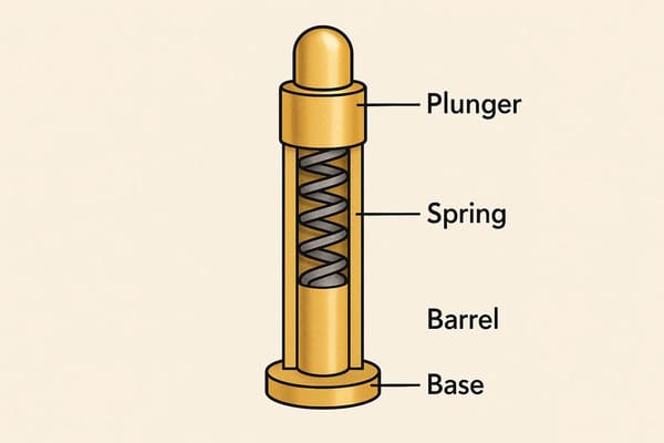
electrical functions and do not necessarily require the same base
material.
Strategy 1: Select the Base Metal from Its Component Function
Copper alloys, stainless steels and other metallic materials each provide
different combinations of conductivity, strength, fatigue behavior,
machinability and corrosion resistance.

The engineering decision should therefore begin with the function of the
component.
Spring Material
The spring primarily needs to maintain the required force through the
expected working stroke and service conditions.
Selection should consider:
- required contact force;
- working stroke;
- expected compression cycles;
- operating temperature;
- available spring geometry;
- corrosion exposure.
One alloy should not be specified simply because it is commonly associated
with high-reliability connectors.
Plunger and Barrel Material
The plunger and barrel have different requirements from the spring.

Relevant considerations can include:- electrical resistance;
- tip wear;
- machining geometry;
- surface-finishing process;
- side-load behavior;
- environmental exposure.
Is Stainless Steel Always Better in Corrosive Environments?
No.

Stainless steels can provide useful corrosion and mechanical properties in
some structures, but they should not automatically replace conductive
copper-based materials throughout the electrical path.

Material selection requires a trade-off between:- corrosion performance;
- electrical conductivity;
- contact geometry;
- manufacturing process;
- mechanical requirements.
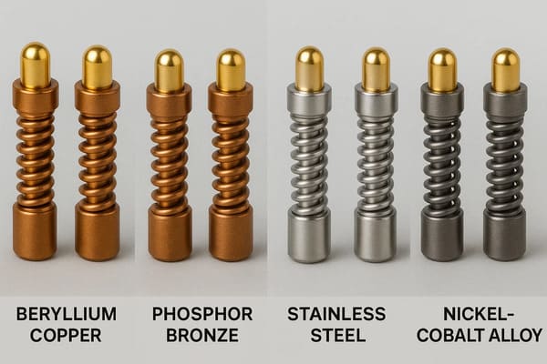
component rather than one universal harsh-environment material rule.
Strategy 2: Treat Plating as Part of the Contact System
Surface finish is important because the electrical interface occurs at the
pogo pin tip and mating target.

However, simply specifying “thicker gold” does not define complete contact
durability.
Surface-finish selection should be evaluated together with:
- pogo pin tip geometry;
- mating target finish;
- working stroke;
- contact force;
- mating motion;
- expected cycle life;
- contamination;
- humidity or chemical exposure.
The Pogo Pin and Target Form One Wear Pair
A durable plunger finish does not solve the problem if the mating target
degrades rapidly.

Both sides should therefore be evaluated as one contact pair:


    Pogo Pin Tip
    ↕
    Contact Interface
    ↕
    Mating Target


Engineers should monitor both surfaces during endurance and environmental
testing.
Plating Thickness Alone Does Not Define Lifetime
Premature degradation can still occur when:- the connector mates at an angle;
- working stroke is excessive;
- abrasive contamination is present;
- contact force is unsuitable;
- the target surface is incompatible;
- lateral sliding is excessive.
Surface finish should therefore be selected as part of the complete wear
system rather than used as a standalone lifetime claim.
working stroke, contact force, wear and environmental exposure.
Strategy 3: Select Housing Materials from Thermal and Chemical Exposure
The insulating housing can influence connector alignment, contact spacing,
working stroke and environmental protection.

Polymer selection should therefore consider more than the peak temperature
listed on a material datasheet.
Relevant questions include:
- What is the continuous operating temperature?
- Is short-term high-temperature exposure expected?
- Will the connector experience thermal cycling?
- Will the component pass through a soldering process?
- Which chemicals, oils or cleaning agents can contact the housing?
- How much dimensional change is acceptable?
- Are adhesives, seals or insert-molded parts also present?
Reflow Resistance Is Not the Same as Field Temperature Rating
A housing that can tolerate a short manufacturing temperature excursion
should not automatically be described as suitable for continuous operation
at the same temperature.

Engineers should separate:- assembly-process temperature;
- continuous operating temperature;
- short-duration operating exposure;
- storage temperature;
- thermal-cycle conditions.
One “High-Temperature Plastic” Does Not Solve the Complete Stack
Even when the housing remains dimensionally stable, the complete connector
can still be limited by:- spring behavior;
- surface finish;
- magnets;
- adhesives;
- gaskets;
- PCB solder joints;
- wire or FPC insulation.
Strategy 4: Treat Magnets as a Separate Material System
Not every harsh environment pogo pin connector is magnetic.

When magnets are included for capture or retention, their material and
environmental protection should be evaluated separately from the electrical
contacts.
Magnet-related considerations can include:
- required capture behavior;
- seated retention;
- temperature exposure;
- corrosion environment;
- coating compatibility;
- mechanical retention inside the housing;
- metallic-debris attraction.
Do Not Specify a Magnet Grade Before Defining the Mechanical Requirement
A stronger magnetic grade does not automatically create a more durable
connector.

Excessive attraction can influence:- closing impact;
- removal force;
- lateral sliding;
- housing stress;
- metallic-debris accumulation.
Capture, seated retention and separation behavior should be defined first,
followed by the magnetic structure required to achieve them.
A Magnet Coating Is Not a Hermetic Seal
A protective coating can form one part of the magnet's environmental
strategy, but it should not automatically be described as creating a
hermetically sealed connector.

Environmental protection still depends on the magnet geometry, coating,
housing, interfaces and complete assembly.
Strategy 5: Design the Complete Environmental Boundary
Material selection alone cannot make a pogo pin connector resistant to
every harsh environment.

The complete environmental boundary may include:- pogo pin feedthroughs;
- connector housing;
- housing-to-device joint;
- gaskets;
- potting or insert molding;
- mating targets;
- PCB, FPC or wire terminations;
- drainage or venting features.
Mated and Unmated Conditions Can Have Different Risks
| Connector State | Environmental Question |
|---|---|
| Fully Mated | Is the intended environmental boundary complete? |
| Partially Mated | Can moisture or contamination reach active contacts? |
| Unmated | Are conductive targets exposed to the environment? |
| After Cleaning | Can residue or trapped liquid remain around the contacts? |
| After Environmental Aging | Have seals, coatings or materials changed? |
Salt Spray Is a Test Condition — Not a Service-Life Prediction
Salt-containing environments can be important for marine, transportation
and outdoor equipment, but a salt-spray result should be interpreted within
the conditions of the test.
A useful specification should define:
- test method;
- sample condition;
- mated or unmated state;
- exposure condition;
- preconditioning;
- post-test cleaning where applicable;
- electrical measurements;
- visual inspection criteria;
- pass / fail definition.
Laboratory exposure duration should not be converted directly into a
guaranteed number of years in the field.
Chemical Compatibility Should Be Tested Against the Actual Fluid
The phrase “chemical resistant” is too broad for an engineering
specification.

Different applications can expose connectors to:- cleaning agents;
- oils;
- coolants;
- fuels;
- lubricants;
- industrial process chemicals;
- skin oils or sweat;
- salt-containing water.
Materials that tolerate one exposure should not automatically be assumed
suitable for another.
Corrosion Can Be an Interface Problem, Not Just a Material Problem
The pogo pin may contain multiple metals, surface finishes and adjacent
conductive structures.

When moisture or another conductive contaminant reaches the interface,
engineers should consider the complete material combination rather than only
the corrosion resistance of one component.
This includes:
- pogo pin finish;
- mating-target finish;
- underlying materials;
- nearby metallic housing;
- PCB finishes;
- fasteners or structural metal;
- environmental electrolyte.
Mechanical Environment Still Matters After Material Selection
Even a carefully selected material system can degrade prematurely if the
connector is mechanically misused.
Examples include:
- excessive working stroke;
- repeated bottoming;
- large lateral loads;
- misalignment;
- housing deflection;
- abrasive sliding;
- structural loads passing through the pogo pins.
Pogo pins should primarily provide compliant electrical contact rather than
act as structural stops.
Working Stroke Must Be Included in Harsh-Environment Validation
Connector material performance cannot be separated from the actual contact
compression.
A simplified relationship is:
S = Hfree - Hseated

The endurance and environmental test should use the intended minimum,
nominal and maximum working conditions rather than an undefined compression.
Electrical Load Can Accelerate Environmental Failure
Environmental degradation can increase the resistance of the complete
electrical path.

As current increases, that resistance can become increasingly important to
voltage drop and heating.
The complete path may include:
    PCB / Wire
    →
    Termination
    →
    Pogo Pin
    →
    Contact Interface
    →
    Mating Target
    →
    Load


For power applications, engineers should measure voltage drop and
temperature rise after relevant environmental and lifecycle exposure rather
than only when the connector is new.
Material Selection Matrix for Harsh Environment Pogo Pins
| Design Area | Key Requirement | Do Not Assume |
|---|---|---|
| Spring | Force stability and fatigue behavior | One alloy is universally best |
| Plunger | Electrical contact and wear | Maximum conductivity automatically means maximum life |
| Barrel | Guidance, structure and electrical path | Stainless steel is automatically superior |
| Surface Finish | Contact and corrosion performance | Thicker gold alone supports durability |
| Mating Target | Compatible contact surface | The target can be ignored during endurance testing |
| Housing | Insulation, geometry and environmental stability | Reflow resistance equals continuous temperature rating |
| Magnet | Capture and retention where required | A stronger magnet is automatically better |
| Seal / Potting | Environmental boundary | Visible sealing features automatically prove an IP rating |
Recommended Harsh-Environment Validation Matrix
| Validation Area | Recommended Evaluation |
|---|---|
| Baseline | Record initial resistance, dimensions, stroke and contact condition |
| Temperature | Evaluate the actual operating and storage profile |
| Thermal Cycling | Review dimensional and electrical change |
| Humidity / Moisture | Evaluate relevant mated and unmated states |
| Corrosive Exposure | Define environment, sample state and acceptance criteria |
| Chemical Exposure | Test actual project-relevant fluids |
| Dust / Debris | Evaluate seating, contact resistance and plunger motion |
| Shock / Vibration | Validate the complete mounted connector assembly |
| Repeated Mating | Monitor pogo pin and target wear |
| Electrical Load | Measure voltage drop and temperature rise where relevant |
| Post-Exposure Inspection | Evaluate corrosion, wear, force and electrical performance |
Information Required for a Harsh Environment Pogo Pin Review
| Project Input | Information to Provide |
|---|---|
| Application | Industrial, automotive, outdoor, marine or other equipment |
| Installation Location | Protected enclosure, exposed surface, engine-adjacent area or other location |
| Temperature Profile | Operating, storage and cycling conditions |
| Moisture Exposure | Humidity, condensation, rain, immersion or cleaning |
| Chemical Exposure | Actual oils, cleaners, salt, coolant or other fluids |
| Mechanical Environment | Vibration, shock, side load and mating motion |
| Pin Map | Function of every contact |
| Electrical Conditions | Voltage, continuous current and peak current |
| Working Stroke | Minimum, nominal and maximum compression |
| Mating Target | Geometry, material and surface finish |
| Lifecycle | Expected mating cycles and end-of-life criteria |
| Environmental Requirement | Required project or customer qualification conditions |
| Project Files | 2D drawing, 3D assembly, PCB layout or interface specification |
Frequently Asked Questions
What are harsh environment pogo pins?
They are spring-loaded electrical contacts designed and validated for a
defined set of environmental stresses such as temperature, moisture,
contamination, chemicals, vibration or repeated mating.
What is the best material for harsh environment pogo pins?
There is no universal best material. The spring, plunger, barrel, mating
target and housing perform different functions and may require different
combinations of conductivity, strength, wear resistance and environmental
compatibility.
Is beryllium copper required for high-reliability pogo pins?
Not universally. Spring and contact materials should be selected from the
required force, stroke, temperature, lifecycle, electrical and environmental
conditions of the specific design.
Does thicker gold plating always increase pogo pin life?
No. Surface-finish durability also depends on contact force, working stroke,
tip geometry, target finish, lateral sliding and contamination.
Are stainless steel pogo pins better for marine environments?
Stainless steel can be useful for selected mechanical or corrosion-related
requirements, but conductivity and complete electrical-path performance
must also be considered. It is not a universal replacement for other pogo
pin materials.
Are high-temperature plastics automatically suitable for automotive or industrial use?
No. Housing selection should consider continuous temperature, short-term
exposure, thermal cycling, chemical compatibility and the limitations of
other connector components.
Does an epoxy-coated magnet make a magnetic connector waterproof?
No. Magnet coating protects only part of the magnetic structure.
Environmental sealing depends on the complete housing, contact feedthroughs,
mating interface and device assembly.
Can salt-spray test hours predict connector life in years?
Not directly. Accelerated corrosion testing should be interpreted under its
defined exposure and acceptance conditions rather than converted directly
into guaranteed field-life years.
Are harsh environment pogo pins automatically IP68?
No. An ingress-protection rating applies only to a defined and tested
connector or complete assembly under specified conditions.
Should the mating target be included in environmental testing?
Yes, when it represents the actual product interface. The pogo pin and
mating target form one electrical and mechanical contact pair.
What information is needed to customize a harsh environment pogo pin?
Provide the installation environment, temperature profile, fluids and
chemicals, vibration conditions, working stroke, mating target, voltage,
current, lifecycle target and mechanical drawings.
Request a Harsh Environment Pogo Pin Engineering Review
Review

    pogo pin and spring-contact solutions

for industrial and project-specific electrical interfaces.

For magnet-assisted removable interfaces, explore

    custom magnetic connector solutions
.

Learn more about CTP manufacturing and engineering capabilities on the

    About Us page
.

Submit your environmental requirements, working stroke, mating target,
voltage, current and product drawings through the

    Get Quote & Samples page
.


    CTP can review pogo pin materials, contact layout, working stroke,
    mating-target structure, surface-finish requirements, housing materials
    and magnetic or non-magnetic connector architectures for harsh
    environment projects. Final corrosion resistance, temperature
    capability, electrical performance, environmental protection and
    lifecycle depend on the approved connector design and project-specific
    validation conditions.