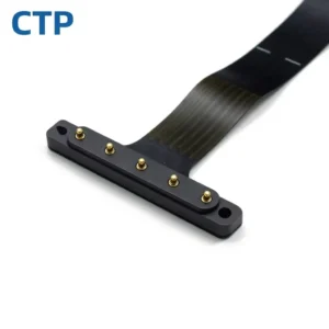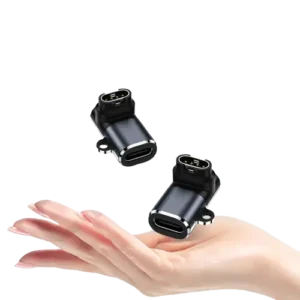
Yes. A magnetic connector contains permanent magnets whose stray field can offset a magnetometer or falsely trigger a Hall sensor or reed switch. The effect is controlled by sensor distance, magnet strength, pole arrangement, and calibration, and it should be tested in both mated and unmated states.
Compact products such as watches and bands feel this problem most, so teams working on magnetic connectors for smart wearables should read on. Medical products add extra sensor and safety constraints; see magnetic connectors for medical devices.
What Is Stray Field in a Magnetic Connector?
Stray field is the magnetic field that extends beyond the connector’s mating face into the surrounding device. It is a by-product of the magnets that provide alignment and retention. The field is invisible and harmless to most electronics, but it becomes a problem when a sensor inside the product measures magnetic fields for its own purpose.
If you want the basics first, read how magnetic connectors work, from magnetic capture to electrical contact.
Why Does a Connector Magnet Disturb a Sensor?
A magnetometer measures the surrounding field, and the Earth’s field is weak, roughly tens of microtesla. A small magnet close to the sensor produces a far stronger local field, so the sensor reads the magnet instead of the planet.
Typical symptoms include:
- Heading offset or drift when the cable is attached
- Lid or dock detection that triggers when charging
- A wake-up switch that behaves differently in the field than on the bench
These faults are intermittent, which is why they often surface late in validation. A similar trap appears when a magnetic connector is attached but not charging, where the real cause sits outside the connector itself.
What Is the Difference Between Hard Iron and Soft Iron Effects?
Hard iron effects come from permanent magnets and add a constant offset to the sensor reading. Soft iron effects come from permeable metals such as steel screws, shields and springs, which bend the surrounding field depending on device orientation.
| Effect | Source | Behaviour | Calibration |
|---|---|---|---|
| Hard iron | Connector magnets, magnetised parts | Constant offset | Usually correctable |
| Soft iron | Steel shields, screws, springs | Orientation-dependent distortion | Harder to remove |
A magnetic connector can cause both. The mated cable adds its own magnet and metal, so the field changes the moment the cable connects.
Does Distance or Magnet Strength Matter More?
Distance matters more. For a small magnet, field strength falls roughly with the cube of distance in the far field, so doubling the gap cuts the disturbance by a large factor. Changing magnet grade rarely achieves the same improvement as moving the sensor.
Practical placement rules:
- Place the magnetometer at the opposite end of the PCB from the connector.
- Avoid positions directly above or below the magnet.
- Keep the sensor clear of board corners near the charging port.
Sensor distance is set early in layout, so plan it alongside the PCB mounting guide for magnetic pogo pin connectors.
How Can You Reduce Magnetic Interference in Your Design?
Start with placement, then adjust magnet size, polarity, orientation, and shielding. Each lever has a different cost and effect.
| Design lever | What it does | Watch out for |
|---|---|---|
| Sensor placement | Increases distance | Limited by enclosure size |
| Right-sized magnet | Cuts field at the source | Must still meet retention force |
| Alternating polarity | Partial cancellation at distance | Confirm pole layout with supplier |
| Magnet axis orientation | Aligns field away from sensor | Verify by measurement |
| Magnetic shielding | Redirects stray field | Can distort the measured field |
| Non-magnetic nearby parts | Avoids soft iron effects | Check springs and housings |
Pole layout is closely tied to pin arrangement, so review it together with magnetic connector contact sequencing.
How Much Retention Force Does a Magnetic Connector Really Need?
Only as much as the application requires. A bedside wearable charger needs less holding force than an industrial cable exposed to snagging. An oversized magnet adds stray field without adding value. Define the minimum retention force first, then size the magnet to it.
Can Firmware Compensate for Connector Magnetic Fields?
Yes, partially. Firmware can remove hard iron offsets through calibration, but the mated and unmated states need different profiles because the field changes when the cable attaches.
Recommended steps:
- Detect charging state from the power path.
- Switch to a matching calibration profile.
- Flag or pause heading output if accuracy cannot be guaranteed.
- Recalibrate after accessory or case changes.
Detecting the charging state depends on a clean power path. See how to design the complete DC power path for magnetic power connectors.
How Do You Test for Connector-Induced Sensor Errors?
Compare sensor output with the cable unmated and mated, across orientations and repeated connections. Early prototype testing is cheap, while fixing the issue after tooling is expensive.
Validation checklist:
- Heading test: unmated vs. mated at several orientations.
- Repeatability: connect and disconnect several times and confirm the reading returns.
- Rotation sweep: full turn with the cable attached.
- Switch trigger test: confirm Hall sensors and reed switches are not set or released unexpectedly.
- Tolerance check: test at the extremes of mating position.
- Temperature check: magnet strength changes with temperature.
Test both conditions the product will see in service, including mated and unmated use. Record results against the drawing revision so future changes can be compared with a baseline.
Frequently Asked Questions
Can a magnetic charging cable damage a phone or watch compass?
It does not damage the sensor, but it can temporarily shift the reading while attached. Accuracy usually returns after the cable is removed, unless the device was calibrated in the presence of the magnet.
Will a magnetic connector trigger a Hall sensor by accident?
It can, if the Hall sensor sits within the connector’s field range. Test approach direction, mating position, and distance during prototyping.
Is magnetic shielding the best fix for sensor interference?
Not usually. Shielding can distort the field the sensor needs to measure, so placement and magnet sizing should be tried first.
Does a magnetic connector affect wireless charging or NFC?
It depends on the product design and layout. Magnetic parts and metal near an antenna can change its behaviour, so verify with the actual assembly.