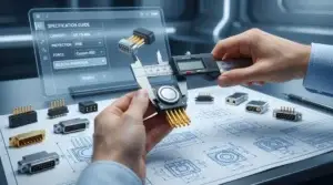
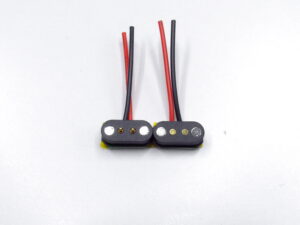
A magnetic pogo pin connector supplier should be evaluated not only by whether the first samples work, but by whether the approved design can be reproduced consistently across pilot production, mass production and future repeat orders.
Many connector projects become unstable after sample approval. A material is changed, a magnet is installed at a different depth, a test fixture wears, a plating source changes or a production line interprets the drawing differently. The connector may still look identical while its retention force, contact resistance, working compression or environmental performance has changed.
For this reason, supplier management must continue after qualification. Engineering and procurement teams need a controlled technical baseline, traceable production records, a formal change-notification process and clear release criteria for every important production stage.
A reliable magnetic pogo pin connector supplier should be able to reproduce the approved design, identify the material and process history of each production lot, notify the customer before important changes and provide objective evidence that repeat orders remain within the released specification.
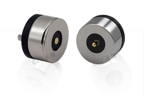
Supplier Qualification Does Not End with a Successful Sample
A prototype or engineering sample normally receives more manual attention than a production part. Engineers may adjust the housing, select matching components or retest the sample until it performs correctly.
Mass production introduces a different question:
Can the supplier reproduce the same functional result using the intended materials, tooling, fixtures, operators and inspection methods?
A supplier can produce a good sample while still having weaknesses in:
- material traceability;
- drawing and revision control;
- magnet-polarity control;
- pogo pin installed-height control;
- adhesive or molding processes;
- test-fixture maintenance;
- sub-supplier management;
- change notification;
- repeat-order verification.
The Three Supplier Release Gates
A custom connector project should normally pass three separate release gates.
| Release gate | Main purpose | Typical evidence |
|---|---|---|
| Design release | Confirms that the connector design meets the agreed application requirements. | Released drawing, pin map, material specification, approved sample and design-test results. |
| Production release | Confirms that the intended production process can reproduce the design. | Pilot lot, inspection records, process flow, fixture approval and production validation. |
| Repeat-order release | Confirms that later orders remain consistent with the approved baseline. | Revision check, lot traceability, key-dimension results and change-status confirmation. |
Approving a design sample should not automatically release unlimited future production.
1. Create a Controlled Technical Baseline
The approved product must be connected to a clear set of controlled documents. Otherwise, the supplier and customer may remember the approved configuration differently.
The technical baseline should normally include:
- customer and supplier part numbers;
- drawing number and revision;
- 3D model revision where applicable;
- pin count and electrical pin map;
- pogo pin structure or approved contact part number;
- pogo pin installed height;
- working compression range;
- magnet dimensions, position and polarity;
- housing material;
- contact and mating-pad finish requirements;
- PCB, FPC, wire or cable termination details;
- adhesive, potting or molding requirements;
- retention-force or breakaway-force criteria;
- electrical test requirements;
- packaging and handling requirements.
Differentiate fixed and adjustable requirements
The released specification should clearly distinguish between:
- fixed characteristics: cannot be changed without approval;
- supplier-controlled characteristics: may be adjusted within an agreed range;
- reference information: does not define acceptance by itself.
Without this distinction, a supplier may treat an important engineering requirement as an optional reference.
2. Link the Approved Sample to a Specific Revision
An approved sample should not exist as an unidentified physical object.
Its record should include:
- part number;
- drawing revision;
- sample-build date;
- material or component lot where available;
- sample quantity;
- test report number;
- approved deviations;
- customer approval status.
Approved sample vs. reference sample
| Sample type | Purpose | Limitation |
|---|---|---|
| Engineering sample | Evaluates the initial design concept. | May contain manual adjustments or prototype materials. |
| Approved sample | Represents an accepted design configuration. | Must still be linked to controlled documentation. |
| Production reference sample | Supports visual or functional comparison during production. | Cannot replace dimensional and electrical specifications. |
| Retention sample | Preserves evidence from a specific production lot. | Represents only that lot and storage condition. |
3. Define Critical Characteristics Before Production
Not every dimension or inspection item has the same effect on connector performance. Engineering teams should identify the characteristics most closely connected to fit, electrical contact and safety.
Possible critical characteristics include:
- pogo pin installed height;
- working compression;
- pin pitch and array position;
- housing flatness;
- magnet polarity;
- magnet installation depth;
- retention or separation force;
- contact resistance;
- continuity and pin mapping;
- cable resistance;
- solder, weld or crimp integrity;
- seal dimensions where applicable.
For each critical characteristic, define:
- nominal value or accepted range;
- measurement method;
- measurement datum;
- inspection equipment;
- inspection frequency;
- record-retention requirement;
- reaction plan after an out-of-specification result.
4. Require Lot Traceability
Traceability allows the supplier and customer to identify which materials, processes and inspections were associated with a production lot.
A practical traceability system may connect the finished connector to:
- production order;
- production date or shift;
- pogo pin lot;
- magnet lot;
- housing material lot;
- PCB, FPC, wire or cable lot;
- plating or surface-treatment lot;
- adhesive, potting or molding-material lot;
- assembly line or station;
- inspection and test records;
- packaging lot.
Why lot traceability matters
When a field problem appears, traceability helps answer:
- Are all products affected or only one lot?
- Was the same pogo pin lot used in other orders?
- Did a material or process change occur?
- Which test records belong to the affected products?
- Which inventory should be contained?
- Which customers or shipments require review?
Without traceability, a small issue can force a much larger and more expensive containment action.
5. Establish a Supplier Change-Control Agreement
One of the most important supplier-management controls is deciding which changes require customer review before implementation.
Changes that may affect connector performance include:
- pogo pin structure;
- spring-force specification;
- plunger-tip geometry;
- contact material;
- plating material or thickness;
- magnet grade, size or supplier;
- housing resin;
- adhesive or potting material;
- PCB or FPC supplier;
- wire or cable source;
- molding tool;
- assembly fixture;
- test method or test limit;
- production line or manufacturing location;
- critical sub-supplier.
A supplier should not determine unilaterally that a change is harmless when it affects a released material, process or critical characteristic.
What a change request should contain
- description of the proposed change;
- reason for the change;
- affected part numbers and revisions;
- comparison of old and new configurations;
- expected dimensional, electrical and mechanical impact;
- validation plan;
- sample availability;
- inventory transition plan;
- proposed implementation date;
- traceability method for old and new production.
6. Control Temporary Deviations Separately
A temporary deviation is not the same as a permanent engineering change.
A deviation may be requested when:
- a material is temporarily unavailable;
- a dimension is outside the normal range but may still be functional;
- a substitute process is required for a limited batch;
- existing inventory must be reviewed before disposal;
- production needs short-term approval while corrective action is completed.
A deviation approval should identify:
- affected quantity;
- affected lot or order;
- specific nonconformance;
- technical risk assessment;
- additional inspection or testing;
- expiration condition;
- labeling or traceability requirement.
Temporary deviation approval should not silently become the new production standard.
7. Verify Sub-Supplier Control
A connector manufacturer may purchase pogo pin components, magnets, plated parts, cables, PCBs, plastics or surface-treatment services from external suppliers.
The direct supplier remains responsible for controlling these sources.
Supplier-management questions should include:
- Which components are made internally?
- Which processes are outsourced?
- How are critical sub-suppliers approved?
- How are incoming materials identified?
- Can the supplier trace a finished lot to a critical sub-supplier lot?
- Can a sub-supplier be changed without customer approval?
- How are plating, heat treatment or molding records controlled?
Do not confuse material declarations with process control
A material declaration can support chemical compliance, but it does not prove that:
- the correct material was used in every batch;
- the plating process remained stable;
- the contact dimensions stayed within tolerance;
- the connector passed the intended mechanical tests;
- the sub-supplier was unchanged.
8. Approve the Production Tooling and Fixtures
Tooling and fixtures can influence connector performance as much as the individual components.
Important production equipment may include:
- pogo pin insertion fixtures;
- magnet-polarity fixtures;
- adhesive-dispensing fixtures;
- molding tools;
- soldering fixtures;
- cable-termination fixtures;
- retention-force test fixtures;
- electrical test fixtures;
- dimensional inspection fixtures.
Fixture-related supplier risks
- fixture wear changes installed height;
- adhesive accumulates on the datum surface;
- test contacts wear and increase measured resistance;
- a replacement fixture is built to a different revision;
- calibration does not include the functional dimension;
- operators compensate manually for fixture variation.
The supplier should maintain fixture identification, maintenance records and revision status for equipment controlling critical characteristics.
9. Use Pilot Production to Verify the Real Process
Pilot production should use the intended production conditions rather than a laboratory-only assembly method.
The pilot lot should use the intended:
- materials and sub-suppliers;
- production tooling;
- assembly fixtures;
- operators or automated stations;
- work instructions;
- inspection methods;
- packaging;
- traceability system.
Questions the pilot should answer
- Can the released dimensions be achieved repeatedly?
- Is magnet polarity controlled without relying only on visual judgment?
- Do all pogo pins remain within the installed-height requirement?
- Does the production test detect open, short and pin-map errors?
- Can production records identify the materials used?
- Does packaging protect the mating surface?
- Can the supplier distinguish reworked parts from normal production?
- Is inspection capacity sufficient for the planned output?
10. Separate Design Validation from Production Verification
Design validation asks whether the connector design can meet the application requirements.
Production verification asks whether the supplier has produced the released design correctly.
| Design validation | Production verification |
|---|---|
| Working-compression range | Actual installed height and mating distance |
| Required retention-force range | Measured force from the production lot |
| Required electrical performance | Production continuity, resistance and voltage-drop results |
| Environmental design target | Correct materials, sealing components and assembly process |
| Mating-cycle requirement | Production part matches the validated structure and revision |
Routine production does not need to repeat every qualification test, but it must confirm that the produced part remains equivalent to the validated configuration.
11. Define the Repeat-Order Verification Package
Repeat orders create risk because both the customer and supplier may assume the product is unchanged.
Before releasing a repeat order, confirm:
- current drawing revision;
- current approved materials;
- open engineering changes;
- open deviations;
- tooling or fixture changes;
- production-location changes;
- sub-supplier changes;
- updated compliance requirements;
- previous lot problems and corrective actions.
Recommended repeat-order evidence
Depending on project risk, the shipment package may include:
- certificate of conformity;
- lot identification;
- revision confirmation;
- critical-dimension results;
- electrical test summary;
- retention-force or cable-test results;
- material or compliance declarations;
- approved-deviation reference;
- inspection report for the production lot.
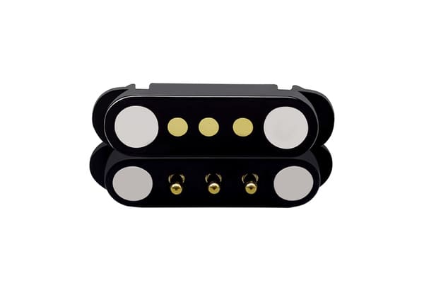
12. Control Rework and Repair
Reworked products may experience additional heat, mechanical handling or component replacement.
The supplier should define:
- which defects may be reworked;
- approved rework instructions;
- maximum permitted rework exposure;
- inspection after rework;
- traceability of reworked parts;
- conditions requiring scrap rather than repair.
Examples of connector rework risks
- reheating damages a pogo pin spring or housing;
- magnet polarity changes during replacement;
- adhesive residue changes the air gap;
- replaced contacts have different installed heights;
- plating is scratched during disassembly;
- sealing components are reused incorrectly.
Rework should not be approved only because the final product passes a basic continuity test.
13. Establish a Nonconformance and Containment Process
When an out-of-specification condition is found, the supplier should first prevent additional affected products from being shipped or used.
Initial containment may include:
- stopping the affected process;
- identifying suspect production time and lots;
- isolating finished goods and work in progress;
- reviewing shipped inventory;
- introducing temporary inspection;
- notifying the customer with the known facts;
- preserving failed samples for investigation.
A useful problem report should distinguish:
- observed symptom;
- confirmed defect;
- root cause;
- escape cause;
- containment action;
- permanent corrective action;
- verification that the action was effective.
Replacing the failed batch without identifying why the problem escaped does not prevent recurrence.
14. Compare Failed and Good Samples
Connector investigations should compare failed samples with known-good samples from the same or nearby lots.
Useful comparisons may include:
- pogo pin installed height;
- working compression;
- contact resistance;
- retention force;
- magnet depth and polarity;
- tip and mating-pad wear;
- housing flatness;
- solder or cable termination;
- material and lot history;
- production-station records.
Analyzing only the failed part can make normal product characteristics look suspicious. Good-sample comparison helps identify meaningful differences.
15. Monitor Supplier Performance by Risk Category
A useful supplier scorecard should separate different types of performance rather than combining everything into one score.
| Category | Possible indicators |
|---|---|
| Engineering response | Drawing accuracy, technical-question response and DFM quality. |
| Sample quality | Sample conformity, documentation and number of correction rounds. |
| Production quality | Incoming failures, lot variation, rework and field issues. |
| Change control | Advance notification, revision accuracy and unauthorized changes. |
| Traceability | Speed and completeness of lot-history retrieval. |
| Delivery | Confirmed lead time, schedule adherence and shortage communication. |
| Corrective action | Containment speed, root-cause quality and recurrence prevention. |
16. Review Capacity by Process Bottleneck
A supplier’s total monthly output does not automatically describe its capacity for a specific custom connector.
Capacity should be reviewed by the process that limits the product, such as:
- precision contact machining;
- plating;
- plastic molding;
- magnet assembly;
- manual wiring or soldering;
- overmolding;
- curing time;
- electrical testing;
- environmental testing;
- final inspection.
Capacity questions for the supplier
- Which process determines the lead time for this part?
- Is the process shared with other high-volume customers?
- Is there alternative equipment or tooling?
- Which operations depend on one trained operator?
- Which materials have the longest replenishment time?
- How quickly can output increase without changing the approved process?
- Will increased volume require new tooling or production lines?
Capacity should be connected to the actual product route rather than a general factory claim.
17. Build a Supply-Continuity Plan
Supplier continuity does not require duplicating every source immediately. It requires understanding which single points of failure could interrupt the project.
Potential risks include:
- one custom molding tool;
- one approved plating source;
- one magnet specification with long replenishment time;
- one test fixture;
- one production location;
- one person holding undocumented process knowledge;
- one proprietary component without an approved alternative.
Possible continuity controls
- spare tooling or replaceable wear components;
- documented fixture drawings;
- safety stock for long-lead materials;
- approved alternative materials where technically acceptable;
- backup test equipment;
- controlled transfer procedures;
- clear ownership of custom tooling and drawings.
Supplier Management Checklist
| Control area | Evidence to request |
|---|---|
| Design baseline | Released drawing, pin map, material list and approved sample reference. |
| Critical characteristics | Inspection items, methods, limits and reaction plan. |
| Traceability | Lot code and links to materials, process and test records. |
| Change control | Notification procedure and list of changes requiring approval. |
| Pilot production | Pilot-lot report, process flow, fixture status and production measurements. |
| Repeat orders | Revision confirmation, lot inspection and change-status statement. |
| Nonconformance | Containment, root-cause and corrective-action process. |
| Supply continuity | Bottleneck analysis, tooling backup and long-lead-material plan. |
Warning Signs After Supplier Approval
Supplier risk may be increasing when:
- drawings and samples use different revisions;
- the supplier cannot identify the material lot used;
- repeat orders have visibly different magnets, housings or cable heads;
- inspection results are reported without measurement methods;
- fixture changes are described as internal matters requiring no notification;
- failed lots are replaced without a root-cause report;
- reworked parts cannot be identified;
- the supplier relies on a reference sample instead of the released drawing;
- capacity claims are not linked to the actual product process;
- sub-supplier changes are discovered only after shipment.
Information to Provide a Magnetic Connector Supplier
Supplier consistency also depends on the quality of the customer’s input. Provide:
- device and application description;
- pin count and pin map;
- continuous and peak current;
- operating voltage;
- signal requirements;
- working-compression range;
- retention or breakaway-force requirement;
- mating direction and permitted misalignment;
- environmental requirements;
- assembly and mounting method;
- expected mating cycles;
- critical characteristics;
- required tests and acceptance criteria;
- change-notification requirements;
- traceability requirements;
- prototype and production forecast;
- 2D drawings, 3D models and mating-part information.
Frequently Asked Questions
How should a magnetic pogo pin connector supplier be managed after sample approval?
Freeze the approved technical baseline, release the production process separately, require lot traceability and establish a formal process for supplier changes, deviations and repeat-order verification.
Does an approved sample supports mass-production quality?
No. A sample proves that one configuration worked. Pilot production must confirm that the intended tooling, materials, fixtures and inspection methods can reproduce it.
What changes should a connector supplier report?
Changes to contacts, springs, plating, magnets, plastics, adhesives, cables, sub-suppliers, tooling, fixtures, test methods or production location may require customer review.
What is the difference between a deviation and an engineering change?
A deviation is normally limited to a defined quantity or time. An engineering change permanently revises the approved product or process baseline.
Why is lot traceability important?
It allows the supplier and customer to identify affected materials, process history, test records, inventory and shipments when a problem occurs.
Should every shipment include a full qualification report?
Usually not. Routine shipments may use a risk-based verification package, while full qualification testing is repeated after significant changes or according to the project plan.
How can repeat-order consistency be checked?
Confirm the revision and change status, then review critical dimensions, electrical results, retention force and material traceability for the new lot.
Does ISO certification supports connector quality?
No. A quality-management certificate may support process governance, but product performance still depends on the specific drawing, controls, inspection evidence and validation results.
Should a supplier supports controlled quality requirements?
No production system can provide a credible universal zero-defect guarantee. A better requirement is documented process control, effective inspection, traceability and rapid corrective action.
How should supplier capacity be evaluated?
Review the bottleneck processes for the specific connector, including critical materials, tooling, assembly, curing, testing and inspection capacity.
Conclusion
Managing a magnetic pogo pin connector supplier requires more than selecting a company with attractive samples or a large product catalog.
The approved design should be converted into a controlled technical baseline containing the drawing, materials, critical dimensions, test limits and approved sample identity. Pilot production should then demonstrate that the intended manufacturing process can reproduce the released design.
Long-term consistency depends on lot traceability, sub-supplier control, tooling maintenance and formal notification before important changes. Repeat orders should be verified against the current approved revision rather than assumed to be identical to previous shipments.
When an abnormal lot occurs, the supplier should contain the affected products, preserve evidence, identify the root and escape causes and verify that corrective actions prevent recurrence.
CTP supports custom development of magnetic pogo pin connectors, magnetic cable assemblies, pogo pin connector assemblies and individual pogo pins.
For a new project, submit the device drawings, pin map, current, working compression, retention requirements, validation criteria and production forecast through our Get a Quote & Samples page. The product specification, production-release plan and repeat-order controls can then be reviewed together.
CTP ENGINEERING PATHS
Choose the right path for your project
Move from application requirements to a connector pair, a data-capable cable assembly, or a charging cable configuration. Final specifications are confirmed against an approved drawing and project validation plan.
Magnetic Connectors
Connector geometry, pin layout, mechanical integration and OEM/ODM review.
Engineering overview → 02Magnetic Data Cables
Power and signal allocation, cable exit, interface selection and assembly review.
Cable engineering → 03Magnetic Charging Cables
Browse the complete cable catalog and shortlist a starting structure for customization.
View cable catalog →