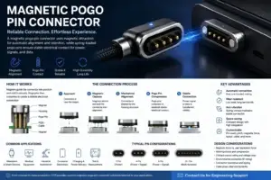
Magnetic pogo pin mass production is the controlled manufacture of spring-loaded contacts, magnets, housings, PCBs, cables and related assemblies using released processes that can repeatedly meet the product specification.
A successful engineering sample does not prove that a production line is ready. Prototype parts may receive manual adjustment, selective component matching or additional inspection that cannot be repeated economically at production volume.
Before mass production begins, engineers should identify the characteristics that determine connector function, validate how those characteristics are measured, establish acceptable process windows and define what production must do when a result moves outside the approved range.
A magnetic pogo pin connector is ready for mass production only when the released drawing, materials, tooling, process parameters, inspection methods, test fixtures and reaction plans can reproduce the approved product without relying on individual operator adjustment or sample selection.
Why Zero-Defect Claims Are Not a Production Strategy
No manufacturing process can credibly supports that every future unit will remain defect-free under every condition.
A more useful production objective is to:
- prevent foreseeable defects through product and process design;
- detect abnormal conditions before affected products are shipped;
- contain suspect material quickly;
- trace affected production lots;
- identify root and escape causes;
- verify that corrective actions prevent recurrence.
Production quality should therefore be evaluated through measurable process performance rather than absolute marketing statements.
Defect Prevention, Detection and Containment Are Different Controls
| Control type | Purpose | Magnetic connector example |
|---|---|---|
| Prevention | Stops the defect from being created. | A keyed fixture prevents a magnet from being installed with reversed polarity. |
| Detection | Identifies a defect after or during the process. | A polarity test identifies an incorrectly installed magnet. |
| Containment | Prevents suspect products from moving forward or shipping. | The line stops and isolates all products made since the previous verified result. |
A final inspection may detect some defects, but it cannot replace stable manufacturing processes.
The Main Stages of Magnetic Pogo Pin Production Readiness
- release the product specification;
- identify critical-to-quality characteristics;
- map the complete production process;
- perform process-risk analysis;
- release the control plan;
- validate measurement and test systems;
- establish process windows;
- validate tooling and error-proofing;
- complete a production-intent pilot build;
- review yield, capacity and reaction plans;
- approve packaging and traceability;
- release mass production.
1. Freeze the Product Definition Before Validating the Process
Production cannot be validated against a design that is still changing informally.
The released product definition should include:
- part number and drawing revision;
- connector dimensions and tolerances;
- pin count and electrical pin map;
- pogo pin structure or approved component number;
- free height and installed height;
- working compression range;
- spring-force requirements;
- contact materials and surface finishes;
- magnet dimensions, grade where specified, location and polarity;
- housing and insulation materials;
- PCB, FPC, cable or wire details;
- adhesive, potting or molding requirements;
- electrical acceptance criteria;
- mechanical-force requirements;
- packaging and labeling requirements.
Production-intent parts must be identified clearly
A pilot build should not combine production tooling with prototype materials without documenting the differences.
Every non-production-intent item should be listed with:
- the temporary configuration;
- the reason it is being used;
- the expected functional impact;
- the plan for production replacement;
- whether repeat validation is required.
2. Identify Critical-to-Quality Characteristics
Critical-to-quality characteristics, often abbreviated as CTQs, are product or process characteristics that have a direct relationship with fit, electrical performance, safety or reliability.
Not every drawing dimension should receive the same inspection level.
Possible magnetic pogo pin CTQs
| CTQ | Functional relationship | Possible control |
|---|---|---|
| Pogo pin installed height | Determines actual working compression. | Controlled insertion fixture and height measurement. |
| Pin pitch and position | Determines alignment with mating pads. | Fixture datum control and dimensional inspection. |
| Magnet polarity | Determines mating orientation and attraction. | Keyed assembly fixture and polarity verification. |
| Magnet depth | Influences air gap and retention force. | Mechanical stop and depth gauge. |
| Contact resistance | Influences voltage drop and heating. | Controlled four-wire or defined functional measurement. |
| Retention force | Determines whether the connector remains engaged and separates as intended. | Force fixture with controlled direction and displacement. |
| Pin map | Prevents open, short and incorrect circuit connections. | Automated electrical test. |
| Cable termination | Influences resistance, pull strength and flex life. | Process parameter control, pull test and electrical testing. |
Each CTQ needs a complete control definition
For every CTQ, specify:
- requirement and tolerance;
- measurement datum;
- inspection method;
- measurement equipment;
- inspection frequency;
- record format;
- reaction after an abnormal result;
- responsible process owner.
3. Map the Complete Production Process
A process flow diagram should show every operation that can affect the finished product.
A magnetic connector process may include:
- incoming pogo pin components;
- incoming magnets;
- incoming molded parts;
- incoming PCB, FPC, cable or wire;
- pogo pin insertion;
- contact height adjustment or seating;
- magnet installation;
- polarity verification;
- soldering or welding;
- adhesive dispensing;
- curing;
- potting or overmolding;
- cleaning;
- dimensional inspection;
- electrical testing;
- mechanical-force testing;
- visual inspection;
- packaging;
- final release.
The flow should also show:
- outsourced operations;
- rework loops;
- inspection points;
- material hold locations;
- lot-code creation;
- scrap disposition.
4. Convert Process Risks into a PFMEA
A process failure mode and effects analysis, or PFMEA, identifies how each production step may create a defect, what effect that defect could have and which controls are required.
The purpose is not to create a document for a customer audit. It is to connect foreseeable process failures to practical controls.
Example magnetic connector process risks
| Process step | Potential failure mode | Possible effect | Preferred control |
|---|---|---|---|
| Pogo pin insertion | Pin installed too high or too low. | Under-compression, bottoming or uneven force. | Controlled-depth fixture plus height verification. |
| Magnet installation | Incorrect polarity. | Repulsion, wrong orientation or failed mating. | Mechanical polarity keying plus automatic confirmation. |
| Adhesive dispensing | Too little, too much or misplaced adhesive. | Loose magnet, changed air gap or contaminated contact. | Programmed dispensing, weight or vision verification and controlled curing. |
| Soldering | Cold joint, bridging or heat damage. | Open circuit, high resistance or reduced mechanical strength. | Released thermal parameters, inspection and functional testing. |
| Overmolding | Component displacement or resin entering the contact area. | Incorrect geometry, stuck plunger or failed mating. | Insert fixture, molding-window validation and post-mold inspection. |
| Electrical test | Fixture contact fails to detect high resistance. | Defective connector released as acceptable. | Fixture correlation, reference standards and maintenance limits. |
Focus on prevention before adding more inspection
When a failure has a serious product effect, the preferred response is usually to improve the process or introduce error-proofing rather than relying only on additional manual inspection.
5. Translate the PFMEA into a Control Plan
The control plan defines what production must control at each process step.
A useful control plan contains:
- process name;
- product or process characteristic;
- specification or approved process window;
- measurement method;
- sample size or inspection frequency;
- recording requirement;
- reaction plan;
- responsible position.
Example control-plan entries
| Characteristic | Control method | Reaction example |
|---|---|---|
| Pogo pin installed height | Fixture setting plus dimensional measurement at the defined frequency. | Stop production, isolate output since the last accepted measurement and inspect the fixture. |
| Magnet polarity | Error-proofed loading plus functional polarity verification. | Stop line and contain all products from the affected fixture cycle. |
| Adhesive amount | Dispensing parameters and periodic mass or vision check. | Hold uncured parts, clean the nozzle and verify the dispensing program. |
| Electrical pin map | Automated open, short and mapping test. | Reject the unit and review the assembly station for systematic wiring or soldering errors. |
6. Validate the Measurement System
A production measurement is useful only when the measurement method can distinguish actual product variation from equipment and operator variation.
Simply using a high-resolution instrument does not prove that the complete measurement system is suitable.
Measurement-system inputs include:
- instrument resolution;
- calibration status;
- fixture repeatability;
- part positioning;
- measurement force;
- operator method;
- environmental conditions;
- software and calculation rules;
- reference standards.
Magnetic connector measurements requiring particular care
- individual pogo pin installed height;
- coplanarity across a multi-pin array;
- spring force at a defined displacement;
- magnetic retention at a defined air gap and pull direction;
- low contact resistance;
- cable pull strength;
- adhesive position or amount;
- housing flatness.
Check repeatability and reproducibility
For important measurements, compare:
- repeated results from the same operator;
- results from different operators;
- results from different fixtures or instruments;
- results from production and laboratory methods;
- measurements across the expected product range.
If measurement variation is large relative to the product tolerance, the inspection result may create false acceptance or false rejection.
7. Establish Process Windows Instead of Single Machine Settings
A released process should define an acceptable parameter range and the evidence supporting that range.
Examples include:
- pogo pin insertion force and depth;
- soldering temperature and time;
- dispensing pressure, time and needle position;
- adhesive curing temperature and duration;
- molding temperature, pressure and hold time;
- crimp height;
- welding energy;
- overmolding parameters;
- test-fixture compression.
Why a nominal setting is insufficient
Production inputs vary because of:
- material lots;
- equipment wear;
- ambient temperature;
- operator loading;
- fixture contamination;
- component tolerances;
- machine-to-machine differences.
The process should produce acceptable parts across its approved operating window, not only at one ideal setting.
8. Validate Pogo Pin Insertion and Installed Height
Pogo pin height directly affects connector compression and contact force.
An insertion process should control:
- part orientation;
- insertion direction;
- support beneath the housing or PCB;
- applied force;
- final depth;
- damage to the barrel or termination;
- fixture wear;
- contact-array coplanarity.
Do not press on the moving plunger
Installation force should be applied to an approved load-bearing area. Pressing directly on the plunger can compress or damage the internal spring mechanism.
Inspect individual contacts, not only average height
An array may meet its average height while one pin remains too low or too high.
Relevant results include:
- minimum individual height;
- maximum individual height;
- range across the array;
- array tilt relative to the functional datum;
- height after soldering, molding or final assembly.
9. Validate Magnet Installation and Polarity Control
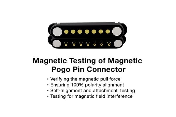
Magnet-related defects may not be detected by a basic electrical test.
Production should control:
- magnet type and dimensions;
- polarity;
- installation orientation;
- installation depth;
- adhesive coverage;
- curing condition;
- foreign material on the mating surface;
- retention after aging.
Magnet grade alone is not a production acceptance criterion
Connector retention also depends on:
- magnet dimensions;
- air gap;
- housing thickness;
- magnetic return parts;
- assembly position;
- total pogo pin spring load;
- pull direction.
Production acceptance should therefore use a functional dimension or force result connected to the final assembly.
10. Validate Adhesive, Potting and Curing Processes
Adhesive and potting processes can affect both mechanical retention and connector geometry.
Possible defects include:
- insufficient adhesive;
- excess adhesive changing the magnet position;
- adhesive entering the pogo pin opening;
- uncured material;
- voids;
- incorrect mix ratio;
- surface contamination;
- movement during curing.
Process controls may include:
- material lot and expiration control;
- mix-ratio control;
- dispensing-program revision;
- needle and nozzle condition;
- dispensed mass or volume;
- vision inspection;
- curing time and temperature;
- fixture retention during curing;
- post-cure mechanical verification.
11. Validate Soldering and Electrical Terminations
Connector performance can be limited by the solder joint, cable termination, FPC or PCB rather than the pogo pin itself.
Production validation should review:
- reflow or soldering profile;
- joint wetting;
- solder volume;
- bridging;
- flux contamination;
- thermal exposure to springs, magnets and plastics;
- connector movement during soldering;
- wire stripping and conductor damage;
- crimp or welding parameters;
- strain relief.
Electrical testing should include the complete path
Depending on the product, the tested path may include:
- pogo pin;
- connector termination;
- PCB or FPC;
- wire or cable;
- solder, crimp or weld;
- mating counterpart.
12. Design Error-Proofing into the Production Line
Error-proofing should make an incorrect assembly difficult or impossible.
Possible magnetic connector error-proofing methods
- fixtures that accept the magnet in only one orientation;
- asymmetric nests for left and right connector variants;
- barcode verification of component and drawing revision;
- sensors confirming all pogo pins are present;
- depth stops for insertion;
- automated dispensing programs locked to the product code;
- test fixtures that reject incorrect pin mapping;
- software preventing production under an obsolete process revision;
- different trays for electrically incompatible variants.
A visual work instruction can support production, but it is normally weaker than physical or electronic prevention.
13. Validate the Production Test Fixture
A test fixture can create misleading results if its contacts, alignment or compression are unstable.
The fixture should control:
- product orientation;
- mating position;
- contact compression;
- electrical measurement path;
- applied load;
- test duration;
- software limits;
- reference standards.
Common fixture-related problems
- worn test probes create high resistance;
- fixture compression hides an under-height production contact;
- misalignment scratches the product contact surface;
- fixture wiring adds unaccounted resistance;
- software uses the wrong product limits;
- a fixture passes the product in one orientation but not another;
- fixture maintenance is based only on time rather than performance.
Correlate production and engineering measurements
Test several known-good, borderline and known-failed samples using:
- the engineering laboratory method;
- the production fixture;
- an independent reference method where practical.
Investigate systematic differences before setting production limits.
14. Decide Which Tests Require 100% Inspection
Not every characteristic should be tested on every unit. The inspection strategy should reflect failure severity, process capability, detection effectiveness and testing cost.
Characteristics often suitable for automated 100% checks
- open circuits;
- short circuits;
- pin mapping;
- wrong polarity where the method is reliable;
- basic functional detection;
- presence of required components;
- barcode and product revision.
Characteristics commonly controlled by process plus sampling
- detailed dimensions;
- spring-force curves;
- plating thickness;
- retention-force characterization;
- destructive pull tests;
- environmental testing;
- mating-cycle durability.
The exact strategy should be project-specific. A test performed on every unit is not automatically effective if the measurement method is unreliable.
15. Conduct a Production-Intent Pilot Build
A pilot build should reproduce the planned mass-production conditions as closely as practical.
It should use the intended:
- production materials;
- approved sub-suppliers;
- tooling;
- fixtures;
- equipment;
- work instructions;
- operators or automation;
- inspection methods;
- test software;
- packaging;
- traceability system.
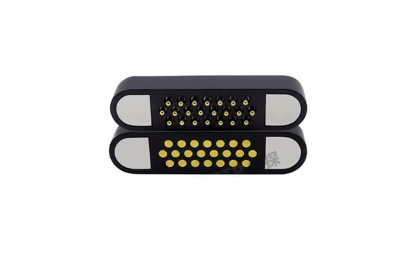
The pilot should answer:
- Can production achieve the critical dimensions repeatedly?
- Do operators understand the released process?
- Do fixtures control the correct functional datums?
- Can the line prevent or detect reversed magnets?
- Can electrical tests identify open, short and mapping errors?
- Can the test system distinguish good and defective products?
- Are rework and scrap clearly identified?
- Can each lot be traced to components, process and test records?
- Does the packaging protect the contacts and magnet surfaces?
- Can the planned output be achieved without bypassing controls?
16. Measure Production Yield Correctly
Final pass rate alone may hide rework and repeated testing.
Useful launch metrics include:
- first-pass yield;
- rolled throughput yield across multiple processes;
- rework rate;
- scrap rate;
- false-fail rate;
- defects per production lot;
- test-fixture downtime;
- cycle time;
- unplanned process adjustments;
- customer or incoming-inspection rejection.
First-pass yield
First-pass yield is the percentage of products that pass a process or final test without repair, adjustment or retesting.
A high final pass rate with a low first-pass yield may indicate hidden production instability.
17. Separate Product Defects from False Test Failures
A failed test result does not automatically prove that the product is defective.
Possible false-failure causes include:
- dirty fixture contacts;
- worn fixture probes;
- incorrect fixture compression;
- software timeout;
- wrong test program;
- unstable power supply;
- operator loading error;
- fixture wiring damage.
Repeated retesting until a product passes is not an acceptable reaction plan.
The process should define:
- how many retests are permitted;
- when fixture verification is required;
- how products with intermittent results are identified;
- whether the original failed result is retained;
- who may release a retested unit.
18. Define the Reaction Plan Before Production Starts
A control plan is incomplete without a reaction to abnormal results.
A reaction plan may require production to:
- stop the affected operation;
- identify the last confirmed acceptable result;
- isolate products made after that point;
- verify the instrument or fixture;
- inspect process parameters and materials;
- correct the process;
- produce and verify restart samples;
- determine the disposition of suspect material;
- document the event;
- escalate repeated or serious abnormalities.
Define the containment boundary
The suspect quantity may be determined by:
- time since the last accepted check;
- material lot;
- machine cycle count;
- fixture change;
- operator shift;
- tooling maintenance;
- test-software revision.
19. Control Rework as a Separate Process
Rework can introduce different risks from normal production.
Examples include:
- additional soldering heat;
- damaged plating during disassembly;
- incorrect replacement magnet polarity;
- changed adhesive thickness;
- mixed pogo pin heights;
- reused sealing parts;
- reduced cable strain relief.
The rework process should specify:
- which defects may be reworked;
- approved rework instructions;
- maximum rework exposure;
- required post-rework tests;
- reworked-product identification;
- conditions requiring scrap.
20. Validate Packaging and Shipping Conditions
A connector that passes production testing may still be damaged during packaging, storage or transport.
Packaging should prevent:
- continuous pogo pin compression;
- contact-to-contact scratching;
- magnetic attraction between loose parts;
- foreign particles reaching the contact face;
- bent cable exits;
- mixed product revisions;
- lost traceability labels;
- moisture exposure where relevant.
Packaging validation may include:
- carton quantity and orientation;
- tray or reel retention;
- drop and handling simulation;
- transport vibration where appropriate;
- inspection after unpacking;
- contact resistance or function after shipment simulation;
- barcode readability;
- lot separation.
21. Establish Lot Traceability
Each finished production lot should be connected to the materials, process and test records used to produce it.
Traceability may include:
- finished-product lot code;
- pogo pin component lot;
- magnet lot;
- housing material lot;
- PCB, FPC or cable lot;
- adhesive or potting lot;
- production date and shift;
- equipment or fixture identification;
- test-software version;
- inspection records;
- rework status;
- shipment record.
Traceability does not prevent defects, but it limits the scope and cost of containment when a problem occurs.
22. Verify Capacity Without Bypassing Quality Controls
Mass-production capacity should be evaluated using the released process rather than an ideal machine speed.
Capacity calculations should consider:
- machine cycle time;
- manual loading time;
- curing or waiting time;
- inspection and test time;
- changeover time;
- fixture quantity;
- planned maintenance;
- yield and rework;
- material replenishment;
- staffing and shift structure.
Run-at-rate or capacity trial questions
- Can the line achieve the target output using the approved controls?
- Does output require reduced inspection or undocumented adjustments?
- Does the bottleneck move when volume increases?
- Can the test system keep pace with assembly?
- Are curing and material-handling limits respected?
- Does increased speed affect adhesive, soldering or installed height?
Mass-Production Launch Readiness Checklist
| Readiness area | Required evidence |
|---|---|
| Product release | Approved drawing, BOM, materials, pin map and acceptance criteria. |
| Process flow | Released production route including outsourced and rework operations. |
| Risk analysis | PFMEA linked to actual process controls. |
| Control plan | Characteristics, methods, frequency and reaction plans. |
| Measurement system | Validated instruments, fixtures, methods and reference samples. |
| Process windows | Approved parameter ranges supported by process trials. |
| Error-proofing | Controls for polarity, part presence, orientation and revision. |
| Pilot production | Production-intent lot with measured yield and CTQ results. |
| Testing | Correlated fixtures, released limits and maintenance plan. |
| Traceability | Finished lots linked to components, process and test records. |
| Packaging | Released packaging verified to protect the connector. |
| Capacity | Target output demonstrated without bypassing approved controls. |
Warning Signs That the Product Is Not Ready for Mass Production
- the sample and production drawings use different revisions;
- critical characteristics have no defined measurement method;
- operators manually adjust parts until they pass;
- magnet polarity depends only on visual judgment;
- the process has one target setting but no approved window;
- the test fixture has not been correlated with engineering measurements;
- retesting is used until a product passes;
- pilot parts use prototype materials or tools without documentation;
- reworked products cannot be identified;
- production output cannot be traced to component lots;
- capacity targets require reduced inspection;
- final continuity is the only production test;
- packaging compresses or scratches exposed contacts;
- there is no documented reaction to an abnormal result.
Frequently Asked Questions
What is magnetic pogo pin mass production?
It is the repeatable manufacture of magnetic spring-loaded connector assemblies using released materials, tooling, process parameters, inspections, tests and traceability controls.
Does a successful prototype prove the connector is ready for mass production?
No. A prototype proves that a configuration can work. Production validation must show that the intended process can reproduce it consistently at the required volume.
What are the most important CTQs for a magnetic connector?
Common CTQs include pogo pin installed height, pin position, magnet polarity and depth, contact resistance, retention force, pin mapping and cable termination. The exact list depends on the product.
Should every connector receive 100% inspection?
Some characteristics, such as open, short and pin-map errors, may be suitable for automated unit-level testing. Other characteristics are better controlled through validated processes and risk-based sampling.
Why is measurement-system validation necessary?
If the instrument, fixture or operator method creates excessive variation, production may accept defective parts or reject acceptable ones.
What is the difference between PFMEA and a control plan?
PFMEA identifies potential process failures and their effects. The control plan defines the production controls, inspection methods, frequencies and reactions used to manage those risks.
How should magnet polarity be controlled?
Use error-proofed loading where possible, followed by a reliable functional or polarity test. Visual inspection alone may be insufficient for similar-looking magnets.
What does first-pass yield indicate?
It shows how many units pass without adjustment, repair or retesting. It can reveal process instability hidden by a high final pass rate.
Can automation supports controlled quality requirements?
No. Automation can reduce selected sources of variation, but equipment, fixtures, materials, software and measurement systems must also be controlled.
How should production capacity be verified?
Run the released process at the intended rate while maintaining the approved inspection, test, curing, traceability and maintenance requirements.
Conclusion
Magnetic pogo pin mass production should begin only after the approved connector design has been converted into a controlled manufacturing system.
The production team must know which dimensions and functions are critical, how they will be measured and what action must be taken when a result becomes abnormal. PFMEA should identify foreseeable process risks, while the control plan converts those risks into line-side controls and reaction plans.
Measurement systems and test fixtures must be validated before their results are used for product release. Pogo pin insertion, magnet polarity, adhesive dispensing, soldering, molding and electrical testing should each operate inside released process windows rather than depend on individual operator adjustment.
A production-intent pilot build should demonstrate acceptable CTQ results, first-pass yield, traceability and capacity using the intended tooling, materials, fixtures and test methods. Mass production should not be released until the line can achieve the required output without bypassing those controls.
CTP supports custom development of magnetic pogo pin connectors, magnetic cable assemblies, pogo pin connector assemblies and individual pogo pins.
For a mass-production readiness review, submit the released drawing, pin map, CTQ requirements, production forecast and validation criteria through our Get a Quote & Samples page or email bella@ytanpogo.com. The process flow, control strategy and pilot-production requirements can then be reviewed together.