
Engineering Summary:
Magnetic pogo pin lifespan should be estimated from the real product mission
profile rather than a universal mating-cycle number. Engineers should first
define how frequently the connector is used, how it mates, whether the
contacts are powered during connection or separation, what working stroke
is applied, what environmental exposure occurs and what condition defines
end of life. A laboratory endurance result becomes useful only when its
test conditions and failure criteria are representative of the intended
application.
Magnetic pogo pin lifespan should be estimated from the real product mission
profile rather than a universal mating-cycle number. Engineers should first
define how frequently the connector is used, how it mates, whether the
contacts are powered during connection or separation, what working stroke
is applied, what environmental exposure occurs and what condition defines
end of life. A laboratory endurance result becomes useful only when its
test conditions and failure criteria are representative of the intended
application.
What Does Magnetic Pogo Pin Lifespan Actually Mean?
The phrase magnetic pogo pin lifespan is often reduced to
one number:
10,000 cycles, a model-specific cycle-life target validated under defined test conditions or 1,000,000 cycles.
From an engineering perspective, that number is incomplete unless the test
conditions are also defined.
Connector lifespan should describe how long a defined interface continues
to meet its required mechanical and electrical performance under a defined
product-use profile.
This means lifespan is not simply:
“How many times can the pogo pin physically move?”
It is closer to:
“For how long does the complete contact interface remain within its
approved performance limits under the conditions experienced by the
actual product?”
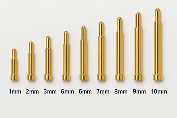
targets, contact forces and wear mechanisms. Lifecycle results should
therefore be associated with the specific connector design.
Start with the Product Mission Profile
Before designing an endurance test, engineers should describe how the
connector will actually be used in the field.

This is the product's mission profile.
A useful mission profile may define:
- connections per day;
- operating days per year;
- required product service life;
- mating and separation direction;
- mating speed;
- expected X-Y or angular variation;
- working stroke;
- electrical load;
- powered or unpowered mating;
- temperature range;
- humidity or moisture exposure;
- dust, sweat, oil or other contamination;
- cleaning or maintenance intervals.
Convert Product Usage into a Required Field Cycle Count
A simple first estimate can begin with:


    Nfield = Cday × Dyear × Yservice
where:
- Nfield = expected field mating cycles;
- Cday = average connection cycles per day;
- Dyear = operating days per year;
- Yservice = required service years.
This calculation does not prove connector life.

It simply translates the product requirement into an initial endurance
target.
Average Usage Is Not Always Enough
Some products have highly variable duty cycles.

For example, one device may connect once per day while another unit in the
same product family is docked dozens of times during one work shift.

Engineers should therefore consider:- typical user behavior;
- high-use users;
- service operations;
- factory test cycles;
- maintenance cycles;
- abnormal repeated docking.
The test requirement should represent the intended reliability target rather
than only the arithmetic average user.
Do Not Add a Universal Safety Factor to Cycle Life
It may be tempting to calculate the expected field cycles and simply
multiply the number by two, five or ten.

There is no universal lifecycle multiplier that is correct for every pogo
pin application.

Any margin should be selected from:- risk level;
- uncertainty in the mission profile;
- sample variation;
- consequences of failure;
- maintenance strategy;
- available qualification evidence.
A large cycle margin also does not compensate for a test condition that
reproduces the wrong failure mechanism.
A Field Cycle and a Laboratory Cycle Are Not Automatically Equivalent
Consider two endurance tests:| Test A | Test B |
|---|---|
| Clean contacts | Representative contamination |
| Room temperature | Application temperature range |
| Unpowered | Powered during intended service state |
| Perfect alignment | Expected tolerance variation |
| Nominal working stroke | Minimum / nominal / maximum stroke |
The same number of cycles in these two tests does not necessarily represent
the same amount of connector degradation.

Therefore:


    Cycle count is a test input. It is not a complete description of
    connector life.

target condition, electrical state and failure criteria represent the
intended product.
Separate the Main Lifespan Damage Mechanisms
Magnetic pogo pin service life is usually influenced by several degradation
mechanisms at the same time.| Damage Mechanism | Possible Effect | Useful Measurement |
|---|---|---|
| Tip / Target Wear | Changes contact surface and geometry | Visual inspection, resistance trend |
| Spring Degradation | Changes contact force | Force at defined stroke |
| Contamination | Changes resistance or seating | Resistance, stroke, visual inspection |
| Corrosion | Changes conductive surfaces | Resistance and surface inspection |
| Repeated Impact | Target, housing or tip damage | Dimensional and visual inspection |
| Electrical Heating | Thermal degradation | Voltage drop and temperature rise |
| Powered Separation | Contact transition damage | Contact surface and transient analysis |
| Magnetic-System Aging | Changes capture or retention behavior | Retention / separation measurement |
Magnetic Retention Does Not Eliminate Contact Separation Risk
Magnets can assist capture and retention, but they do not automatically
supports continuous electrical contact under every vibration or shock
condition.

Connection stability still depends on:- mechanical retention;
- module mass;
- working stroke;
- spring force;
- mechanical datums;
- target flatness;
- structural vibration;
- off-axis load.
A stronger magnet should therefore not be treated as the universal solution
to intermittent contact.
Micro-Interruption Should Be Measured, Not Assumed
If the application is sensitive to brief contact interruptions, the
validation plan should define:- the monitoring bandwidth;
- the allowed interruption duration;
- the electrical load;
- the mechanical excitation;
- the acceptance threshold.
Simply observing that the connector remains physically attached does not
prove that the electrical path remained uninterrupted.
Working Stroke Changes the Lifespan Test
Pogo pin compression directly affects the mechanical and electrical contact
condition.
A simplified relationship is:
S = Hfree - Hworking

The endurance test should therefore reproduce the actual installed
compression range.| Stroke Condition | Possible Effect on Life |
|---|---|
| Too Little Compression | Unstable contact or higher resistance |
| Intended Working Range | Designed contact condition |
| Excessive Compression | Higher mechanical load and potential wear |
| Unequal Compression | Different degradation rates across the array |
The Mating Target Must Stay in the Lifespan Model
A pogo pin does not wear in isolation.

Its mating target experiences the same connection cycles.

If the final product uses one target for its complete service life, the
qualification test should normally evaluate that target as part of the
contact system.

Replacing a worn target repeatedly during the laboratory test can produce a
different wear history from the real product.
Electrical Load Changes What “One Cycle” Means
Mechanical cycling and powered cycling answer different engineering
questions.| Test Condition | Primary Question |
|---|---|
| Unpowered Mating | How does repeated mechanical contact wear? |
| Powered While Seated | How does the contact behave electrically and thermally during service? |
| Powered Mating | What happens during electrical engagement? |
| Powered Separation | What happens while the electrical path opens? |
If the field product never connects or disconnects under load, a powered
mating test may represent an abnormal condition.

If the product routinely separates under current, an unpowered endurance
test may miss an important damage mechanism.
Temperature Rise Should Be Rechecked During the Life Test
Contact degradation may increase complete-path resistance over time.The relationships are:
Vdrop = I × Rpathand:
Ploss = I² × Rpath

This means a connector that operates thermally within limits when new may
behave differently after wear, contamination or corrosion has changed the
interface resistance.

For relevant power applications, temperature-rise measurements should
therefore be repeated at defined lifecycle intervals rather than only at
cycle zero.
Measure Degradation at Intervals Instead of Waiting for Final Failure
A test that records only:

Cycle 0 → Cycle 100,000

misses most of the degradation history.

A better endurance plan uses defined inspection or measurement intervals.
A typical data set may include:
- contact resistance;
- resistance variation;
- intermittent events;
- contact force;
- working-stroke behavior;
- target condition;
- pogo pin tip condition;
- magnetic retention;
- temperature rise.
The actual interval should follow the expected degradation mechanism rather
than one universal inspection schedule.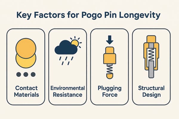
environmental degradation rather than relying on one material or cycle
count alone.
Define End of Life Before Starting the Test
A connector cannot “pass a model-specific cycle-life target validated under defined test conditions” unless the engineering team has
defined what PASS means.
Possible end-of-life criteria may include:
| Metric | Possible Failure Definition |
|---|---|
| Contact Resistance | Exceeds the project-approved limit |
| Intermittency | Exceeds the allowed interruption criterion |
| Contact Force | Falls outside the approved range |
| Working Stroke | Plunger no longer moves or seats as specified |
| Voltage Drop | Exceeds the system requirement |
| Temperature Rise | Exceeds the validated thermal limit |
| Target Wear | Exceeds the project-defined wear criterion |
| Magnetic Retention | Falls outside the defined mechanical range |
| Mechanical Damage | Housing, target or pogo structure becomes unacceptable |
These limits should come from the product requirement rather than from a
generic pogo pin datasheet.
One Sample Does Not Establish Product Lifespan
Suppose one connector survives a target number of cycles.

That result demonstrates what happened to that sample under that test.

It does not automatically establish the life distribution of all production
connectors.

Population-level reliability requires additional consideration of:- sample quantity;
- manufacturing-lot variation;
- test-to-test variation;
- failure distribution;
- samples that have not failed when testing ends;
- confidence requirements.
Use Statistical Life Metrics Carefully
For projects that require population-level reliability analysis, engineers
may use statistical lifetime models such as Weibull or other appropriate
distributions.

One useful reliability concept is B10 life.

Under defined conditions, B10 represents the life at which 10% of the
modeled population has failed and 90% remains surviving.

However, a B10 number should not be reported unless:- the test population is representative;
- the failure definition is consistent;
- sample quantity is appropriate;
- right-censored samples are treated correctly;
- the selected statistical model fits the data reasonably.
A single specimen reaching one million cycles is therefore not the same as
demonstrating one-million-cycle population reliability.
Accelerated Testing Requires Failure-Mechanism Equivalence
Product teams often want to accelerate a long lifecycle test.

Increasing mating speed, temperature, force or environmental severity can
shorten test time.

But acceleration becomes invalid when the harsher test creates a different
damage mechanism from the field application.
For example:
- excessive mating speed may introduce impact damage not present in use;
- excessive compression may create spring bottoming;
- unrealistic temperature may change polymer or magnet behavior;
- high electrical load may create heating that the field product never experiences.
Accelerated-life testing should therefore answer:


    “Are we accelerating the same failure mechanism, or creating a new one?”
Do Not Convert Salt Spray, Temperature or Humidity Hours Directly into Mating Cycles
Mechanical wear, corrosion and thermal aging are different degradation
mechanisms.

A certain number of hours in humidity or corrosion testing should not be
converted directly into a number of mating cycles unless a validated
relationship has been established for the specific product.

In many projects, the stronger approach is to combine the stresses in a
mission-profile-based qualification matrix rather than pretend they are one
interchangeable lifetime unit.
Build a Mission-Profile Qualification Matrix
| Field Condition | Qualification Question | Possible Test Element |
|---|---|---|
| Frequent Daily Docking | Does repeated mating cause unacceptable wear? | Mating endurance |
| Powered Operation | Does resistance drift create unacceptable heating? | Voltage-drop and temperature-rise testing |
| Temperature Cycling | Does dimensional change affect stroke or contact? | Thermal cycling |
| Moisture / Humidity | Does environmental exposure change electrical performance? | Environmental aging plus post-test measurement |
| Dust / Debris | Can contamination prevent final seating? | Representative contamination test |
| Shock / Vibration | Does the interface remain electrically stable? | Mounted assembly monitoring |
| Repeated Cleaning | Do surfaces, seals or targets degrade? | Application-specific cleaning cycle |
Magnetic Lifespan and Pogo Pin Electrical Lifespan Are Not the Same Metric
The magnetic system and electrical contact system can degrade independently.

For example:- electrical contacts may remain functional while seated retention changes;
- magnetic retention may remain stable while contact resistance increases;
- housing wear may affect final alignment without changing magnet strength;
- metallic debris may alter seating while both individual components remain intact.
A magnetic pogo connector lifespan test should therefore measure both the
electrical contact system and relevant mechanical attachment behavior.
Field Data Should Close the Lifespan Model
Laboratory qualification is only one stage of lifecycle engineering.

After production launch, field data can reveal whether the assumed mission
profile was accurate.
Useful field information may include:
- actual docking frequency;
- connection retry events;
- intermittent-contact faults;
- temperature-related events;
- service replacement frequency;
- returned-unit failure analysis;
- target and contact wear condition.
The engineering team can then compare:


    Assumed Mission Profile
    ↕
    Qualification Test
    ↕
    Actual Field Behavior


This feedback loop is much more useful than treating the original cycle
rating as a permanent fixed truth.
Lifecycle Claims Should Be Version-Controlled
A connector's validated life can change when the design changes.Examples include changes to:
- pogo pin structure;
- spring design;
- contact force;
- surface finish;
- mating target;
- housing tolerance;
- magnet structure;
- PCB installation height;
- assembly process.
Lifecycle data should therefore be associated with a controlled drawing or
connector revision.
Supplier Data Should Include Test Conditions, Not Just a Cycle Number
When reviewing a magnetic pogo pin supplier, engineers should ask for the
conditions behind the lifecycle result.
A useful test record may identify:
- connector model and revision;
- sample quantity;
- working stroke;
- mating target;
- electrical state;
- environment;
- mating speed;
- measurement method;
- measurement interval;
- failure criteria;
- final sample condition.

sample information, measurement method and defined acceptance criteria.
Recommended Magnetic Pogo Pin Lifespan Qualification Plan
| Stage | Engineering Output |
|---|---|
| 1. Define Mission Profile | Expected mating frequency, environment and electrical duty |
| 2. Define Required Service Life | Target product years and expected field cycles |
| 3. Define Failure Criteria | Electrical and mechanical end-of-life thresholds |
| 4. Define Test States | Stroke, alignment, target, powered / unpowered conditions |
| 5. Establish Baseline | Initial resistance, force, geometry and retention |
| 6. Run Interval Measurements | Degradation trend rather than final pass only |
| 7. Apply Environmental Stress | Application-relevant moisture, temperature and contamination |
| 8. Analyze Population Data | Variation, failures and censored samples where applicable |
| 9. Compare Against Requirement | Qualification decision |
| 10. Monitor Field Performance | Update mission profile and future validation |
Information Required for a Magnetic Pogo Pin Lifespan Review
| Project Input | Information to Provide |
|---|---|
| Application | Charging, docking, wearable, industrial module or another interface |
| Required Service Life | Expected product operating years |
| Mating Frequency | Expected cycles per day / week / service event |
| Working Stroke | Minimum, nominal and maximum compression |
| Mating Target | Geometry, material and surface finish |
| Electrical Load | Voltage, continuous current and peak current |
| Mating State | Powered or unpowered connection / separation |
| Mechanical Conditions | Mating direction, speed, offset and angular tolerance |
| Environment | Temperature, humidity, water, sweat, dust, oil or chemicals |
| Failure Criteria | Resistance, force, intermittency, thermal or wear limits |
| Maintenance | Cleaning, inspection and replacement plan |
| Project Files | Connector drawing, 3D assembly, PCB layout or interface specification |
Frequently Asked Questions
How long does a magnetic pogo pin connector last?
There is no universal lifespan. Service life depends on working stroke,
mating target, contact force, electrical load, environment, mating motion
and the criteria used to define failure.
Can magnetic pogo pins last one million cycles?
A specific design may achieve a high cycle result under defined conditions,
but that result should not be transferred to another connector or
application without reviewing the test conditions.
Does adding magnets increase pogo pin lifespan?
Magnetic capture or retention can change mating behavior, but magnets do
not automatically eliminate wear, intermittency or other contact failure
mechanisms.
How do I calculate the required pogo pin cycle life?
Begin with expected connection frequency, operating days and product service
life to estimate field cycles, then design the qualification program around
the actual mechanical, electrical and environmental duty profile.
Are laboratory cycles equal to field cycles?
Not automatically. Alignment, working stroke, electrical load,
contamination, temperature and mating speed can make laboratory and field
degradation very different.
Should pogo pin lifecycle testing be powered?
It depends on the actual product use. If the connector mates or separates
while energized in service, the validation plan may need to reproduce that
state.
What defines end of life for a pogo pin connector?
End of life should be defined from project-specific electrical and
mechanical limits such as resistance, intermittency, force, voltage drop,
temperature rise, target wear or retention.
Can accelerated testing predict pogo pin lifespan?
It can support life evaluation when the accelerated conditions preserve the
same relevant failure mechanism. Overstress that creates a new failure mode
may not represent field life.
Does one sample passing the target cycles prove product lifespan?
No. One sample describes that test specimen. Population-level reliability
requires representative samples and appropriate statistical treatment.
What is B10 life for a connector?
B10 life is a statistical reliability metric representing the modeled life
at which 10% of a population has failed under defined conditions. It
requires sufficient and appropriate test data.
Should the mating target be included in a lifespan test?
Yes when it represents the real product. The pogo pin and target form one
wear pair and should normally be evaluated together.
What test data should a pogo pin supplier provide?
Useful data includes connector revision, sample quantity, working stroke,
mating target, electrical state, environment, measurement method, inspection
intervals and pass / fail criteria.
Request a Magnetic Pogo Pin Lifespan Engineering Review
Explore

    custom magnetic connector solutions

for removable charging, docking and modular product interfaces.

Review

    pogo pin and spring-contact solutions

for project-specific contact structures and mounting requirements.

Submit your required service life, expected mating frequency, working
stroke, mating target, electrical load, environmental conditions and project
drawings through the

    Get Quote & Samples page
.


    CTP can review mission profile, pogo pin working stroke, mating targets,
    electrical load, magnetic behavior and lifecycle test conditions for
    custom magnetic connector projects. Final lifespan should be associated
    with the approved connector revision, representative qualification
    conditions and clearly defined end-of-life criteria rather than a
    universal mating-cycle claim.


