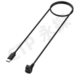
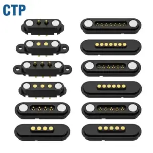
A custom magnetic connector can replace the physical charging or docking interface used by a USB-C receptacle or barrel jack in selected products. It does not automatically replace USB data protocols, USB Power Delivery negotiation, third-party accessory compatibility or regulatory requirements. Barrel jacks are generally easier to replace because they are commonly used as dedicated power interfaces, while replacing USB-C requires a clear decision about which USB functions must be preserved.
The correct question is not simply whether a magnetic connector can replace USB-C or a barrel jack.
Engineers first need to define which functions the existing port currently performs.
An external connector may provide:
- Basic DC power input
- Negotiated power delivery
- Battery charging
- USB data communication
- Firmware updates
- Factory programming and diagnostics
- Video or other alternate functions
- Mechanical retention
- User-detachable cable connection
- A standardized accessory ecosystem
A

    custom magnetic connector

can often replace the mechanical port and selected electrical paths. Replacing the complete functional and commercial ecosystem is a much larger system decision.
The Direct Answer
| Existing Interface | Can a Magnetic Connector Replace It? | Primary Condition |
|---|---|---|
| Barrel jack used only for DC input | Frequently possible | Voltage, current, polarity, exposed-contact safety and cable identification must be defined |
| USB-C used only as a fixed-voltage charging input | Possible in selected devices | The required charging source and device-side control circuit must be redesigned |
| USB-C with USB Power Delivery | Possible only with additional system design | Power negotiation and source compatibility must be retained elsewhere in the architecture |
| USB-C carrying USB data | The physical port may be replaced | The complete magnetic connector, PCB and cable channel must support the required data function |
| USB-C with high-speed data or alternate functions | Usually difficult | Signal integrity, contact count, cable construction and protocol validation become major requirements |
| USB-C required by market regulation | Not necessarily as the only external port | A compliant USB-C receptacle may still need to remain accessible and operational |
| Docking connector inside a proprietary product system | Often suitable | The manufacturer controls both connector halves, electronics and accessories |
Three Different Meanings of “Replace”
1. Mechanical Replacement
The original receptacle is removed and a custom magnetic interface occupies its position in the enclosure.This changes:
- Connector outline
- Installation depth
- PCB footprint
- Cable-removal behavior
- Enclosure opening
- Sealing architecture
- Mechanical load path
Mechanical replacement does not prove that the original electrical functions have been preserved.2. Electrical Replacement
The magnetic connector carries the same required voltage, current and selected signals as the original interface.This requires review of:
- Pin Map
- Voltage range
- Continuous and peak current
- Power-enable logic
- Data functions
- Ground and shield paths
- Protection circuits
3. Ecosystem Replacement
The product no longer depends on the standard cables, chargers, accessories and service tools associated with the original interface.This affects:
- Accessory availability
- Field replacement
- Service procedures
- User expectations
- Regional regulations
- Product certification
- Long-term supply of proprietary cables
Ecosystem replacement is normally the most important commercial difference between USB-C and a custom magnetic interface.Why Barrel Jacks Are Usually Easier to Replace
A barrel jack is commonly used as a dedicated DC power input. Its system function may be limited to positive power and return, although some versions include switching or detection contacts.A magnetic replacement may therefore require:
- Two or more power contacts
- Defined polarity
- Appropriate PCB or wire termination
- Short-circuit protection
- Valid-connector detection where needed
- Mechanical support
- A matching cable or power adapter
Do Not Copy Only the Voltage and Current Label
The replacement interface should be developed from the complete power architecture.Define:
- Nominal input voltage
- Minimum and maximum voltage
- Continuous current
- Startup or inrush current
- Peak load and duration
- Reverse-polarity response
- Short-circuit response
- Maximum permitted voltage drop
- Maximum permitted temperature rise
A barrel jack replacement may need more than two contacts when the product requires adapter identification, temperature sensing or charging authorization.Why USB-C Is More Difficult to Replace
USB-C is not simply a reversible power connector. Depending on the product, the port may participate in power negotiation, device-role detection, USB communication and other system functions.Before removing the USB-C receptacle, identify whether the product uses:
- Basic USB power
- USB Power Delivery
- USB 2.0 data
- Higher-speed USB data
- Device or host-role switching
- Accessory identification
- Firmware recovery
- Factory diagnostics
- Video or other alternate functions
Removing the physical USB-C receptacle does not remove the need for these functions. They must either be transferred to the magnetic connector, moved to another service port, handled wirelessly or removed intentionally from the product specification.A Magnetic Connector Is Not Automatically a USB Connector
A magnetic interface can carry signals assigned to USB functions, but it should not be marketed as USB-compatible based only on Pin count or continuity.Complete-channel performance may depend on:
- Contact layout
- Signal-return path
- Ground allocation
- Contact spacing
- Connector transition
- PCB routing
- Cable construction
- Shield continuity
- Crosstalk
- Partial-mating states
A four-contact magnetic connector may physically carry power, ground and a differential signal pair. This does not by itself establish USB compliance, a specific data rate or USB Power Delivery capability.
Four Practical Replacement Architectures
Architecture 1: USB-C Power Adapter to Magnetic Device Connector
The external power supply uses a standard USB-C output, while the device uses a proprietary magnetic connector.The cable or adapter may contain:
- USB-C plug
- Power-negotiation electronics where required
- Voltage conversion or protection
- Magnetic cable-side connector
- Identification components
- Strain relief and overmolding
Possible benefits:
- The charger side can remain part of the USB-C ecosystem
- The device receives a low-insertion-force interface
- The proprietary electronics remain inside a replaceable accessory
Primary risks:
- The magnetic cable becomes a required proprietary accessory
- Incorrect third-party adapters may not provide the expected power
- Cable-side electronics require qualification and thermal review
Architecture 2: USB-C and Magnetic Connector on the Same Device
The device keeps USB-C for compatibility, service or regulatory reasons and adds a magnetic dock or charging interface.This architecture may be appropriate when:
- USB-C is needed for field compatibility
- A magnetic dock improves daily charging
- USB-C is retained for firmware recovery
- The magnetic interface is used in a fixed workstation
- The device is sold into different markets
Review:
- Power-source arbitration
- Whether both inputs can be connected simultaneously
- Backfeeding prevention
- Charging-controller behavior
- Enclosure and PCB space
Architecture 3: Magnetic Dock with USB-C Upstream Connection
The device connects to a proprietary magnetic dock. The dock connects to the host or power supply through USB-C.

This architecture is useful when the dock can contain protocol, power and identification electronics that would be difficult to place inside the magnetic connector itself.
Possible dock functions include:
- USB Power Delivery negotiation
- Power conversion
- Current limiting
- Device detection
- Data bridging
- Charging-status indication
- Mechanical guidance
Architecture 4: Dedicated Magnetic DC Input
The magnetic connector directly replaces a barrel jack and carries a project-specific DC input.

This is usually the simplest architecture, but the product manufacturer becomes responsible for controlling the cable, power source, polarity and accessory compatibility.
When a Magnetic Interface Is a Strong Candidate
A custom magnetic connector may be a good starting point when the device requires:
- Frequent docking or charging
- Low insertion force
- A controlled breakaway cable
- A shallow or flat device-side interface
- Glove-operated docking
- A proprietary charging case or cradle
- A device-specific connector shape
- Contacts integrated into a sealed enclosure architecture
- A replaceable cable-side spring-contact mechanism
Typical project categories may include:
- Wearable devices
- Charging docks
- Medical and personal-care equipment
- Rugged handheld terminals
- Industrial tablets
- Removable sensor modules
- Robotic accessories
- Custom battery modules
Application suitability must still be confirmed from the electrical, mechanical, environmental and regulatory requirements.When USB-C Is Usually the Better Choice
USB-C normally remains the stronger architecture when the product requires:
- Compatibility with common chargers and cables
- Standardized power negotiation
- High-speed USB functions
- Broad third-party accessory support
- Simple field replacement of cables
- Consumer familiarity
- Compliance with a market requirement for a USB-C receptacle
A product should not replace USB-C only because a magnetic connector appears smaller or easier to use.When a Barrel Jack May Still Be the Better Choice
A barrel jack can remain appropriate when the product requires:
- A simple dedicated power input
- Low component cost
- Established adapters already used by the customer
- No frequent user docking
- No requirement for breakaway behavior
- No need for a custom cable ecosystem
Some industrial applications also prefer locking DC connectors where accidental separation must be prevented. In such cases, magnetic release may be the opposite of the desired behavior.Engineering Comparison
| Selection Factor | USB-C | Barrel Jack | Custom Magnetic Connector |
|---|---|---|---|
| Primary strength | Standardized power and data ecosystem | Simple dedicated DC input | Custom mechanical interface and user interaction |
| Accessory availability | Broad | Broad, but dimensions and polarity vary | Normally controlled by the device manufacturer |
| Power negotiation | Available through the USB system | Normally external or fixed | Must be designed into the system where required |
| Data capability | Defined by the implemented USB functions | Normally none | Project-specific and requires validation |
| Connector geometry | Standardized | Selected from available families | Can be developed around the product |
| Insertion method | Mechanical insertion | Mechanical insertion | Magnet-assisted approach and controlled compression |
| Breakaway behavior | Not normally the primary design function | Depends on the jack and plug | Can be engineered through retention and release requirements |
| Environmental sealing | Depends on connector and enclosure design | Depends on connector and enclosure design | Depends on the complete connector and enclosure design |
| Tooling and development | Mostly standard component integration | Mostly standard component integration | May require custom housing, tooling and validation |
| Service replacement | Common cables are widely available | Replacement requires the correct size and polarity | Requires a matching proprietary cable or dock |
| Regulatory impact | May satisfy applicable common-port requirements | Depends on product and market | Must be checked against product-specific market requirements |
Define the Magnetic Connector Pin Map
The replacement connector may need more contacts than the original port appears to use.| Contact Function | Why It May Be Required |
|---|---|
| Positive power | Primary energy path |
| Power return | Return-current path |
| Detection | Confirms that the connector is seated |
| Identification | Recognizes the approved cable, dock or adapter |
| Temperature sensing | Monitors the connector or charging interface |
| Data contacts | Supports required service or communication functions |
| Shield or chassis | Supports an intentionally defined EMC architecture |
The Pin Map should be approved before the housing, PCB footprint, magnets and mating targets are finalized.Design the Complete Power Path
The current path may include:
- External power source
- USB-C adapter, DC adapter or dock electronics
- Cable conductors
- Cable-side connector termination
- Magnetic connector contacts
- Device-side target contacts
- Device PCB
- Protection and charging circuits
- Battery or electrical load
Define:
- Operating voltage range
- Continuous current
- Peak current and duration
- Duty cycle
- Maximum permitted voltage drop
- Maximum permitted temperature rise
- Ambient-temperature range
- Working stroke during the power test
- Wire size and PCB copper structure
Do not transfer a current rating directly from the removed USB-C or barrel jack to the new connector. The complete new path must be evaluated.Parallel Contacts Require Current-Sharing Validation
Two or more contacts may be connected in parallel for power or return, but current should not be assumed to divide equally.Current sharing can be affected by:
- Pogo pin working-stroke variation
- Contact-resistance variation
- Mating-pad alignment
- PCB-routing differences
- Wire and solder-joint variation
Individual path voltage drop and temperature should be checked where parallel contacts carry meaningful current.Control Exposed Contacts and Partial Mating
Magnetic connectors may use flat, visible device-side contacts. Their electrical state must be defined while the cable is disconnected.Review:
- Whether exposed power contacts are energized
- Short circuit caused by a metal object
- Moisture bridging adjacent contacts
- Incorrect cable or accessory
- Reverse polarity
- Offset mating
- One-contact-first conditions
- Power during separation
Example Power-Enable Sequence
- The connector is disconnected and device-side power is controlled.
- The cable approaches the device.
- Magnets begin assisting alignment.
- Detection or identification becomes valid.
- The system confirms polarity and connector state.
- Charging power is enabled.
- The system monitors current, voltage and temperature.
- Power is removed when valid mating is lost.
The actual sequence should follow the product electronics and risk assessment.Breakaway Is a Design Requirement, Not an Automatic Feature
Magnetic attachment can support controlled release, but real behavior depends on connector geometry and load direction.Test:
- Axial pull
- Side pull
- Peel from the connector edge
- Cable twist
- Pull at the intended cable exit angle
- Pull while the device is supported differently
A connector may resist axial loading while releasing much more easily under peel. The product requirement should define both retention and release conditions.The preferred mechanical load path is:
Cable → connector housing → device enclosurerather than:
Cable → pogo pins → solder joints → unsupported PCBWaterproofing Is Not Determined by Connector Type Alone
USB-C, barrel jacks and magnetic connectors can all be incorporated into sealed product structures. None is automatically waterproof or non-waterproof solely because of its connector family.Potential leakage paths for a magnetic connector include:
- Contact-to-housing interface
- Magnet-to-housing interface
- Housing-to-enclosure interface
- PCB, FPC or wire entry
- Adhesive interfaces
- Cable-side overmolding
Any IP claim should identify the complete tested enclosure, connector state and test condition.Magnetic Interfaces Introduce Their Own Risks
Design teams should also consider:
- Attraction of ferrous debris
- Partial contact held by magnetic force
- Interaction with Hall sensors or magnetometers
- Proprietary cable replacement
- Incorrect third-party accessories
- Magnet assembly and polarity control
- Changes in magnetic behavior with temperature and air gap
- Additional housing and tooling requirements
A magnetic connector is not a universal improvement. It exchanges the limitations of a standard port for a different set of engineering and ecosystem requirements.Total Cost Should Include the Complete Product Lifecycle
Compare more than connector unit price.
| Cost Area | Questions to Evaluate |
|---|---|
| Component cost | What is the connector, cable, magnet, housing and electronics cost? |
| Tooling | Are custom molds, fixtures or gauges required? |
| Development | How much electrical, mechanical and validation work is required? |
| Assembly | Does the custom design simplify or complicate production? |
| Warranty | Could the new interface reduce port damage or introduce accessory failures? |
| Service | How will replacement cables be supplied several years later? |
| Certification | Which tests must be repeated after changing the interface? |
| Customer support | Will users understand that a proprietary cable is required? |
Regulatory and Market Requirements
Connector replacement should be reviewed against the regulations of every intended market.

In the European Union, certain categories of radio equipment capable of wired charging are required to include an accessible and operational USB Type-C receptacle. Additional proprietary connectors may be used, but the magnetic interface may not be permitted to replace the required USB-C receptacle completely.

The affected product category, charging capability, market-entry date and applicable harmonized standards should be confirmed for the actual device.This guide provides an engineering framework and is not legal advice. Confirm market-specific charging-port, safety, EMC, medical, industrial and product-certification requirements with the responsible compliance team.
Replacement Decision Matrix
| Project Situation | Recommended Starting Direction |
|---|---|
| Simple proprietary DC input | Evaluate direct barrel-jack replacement |
| USB-C used only for low-power charging | Evaluate magnetic replacement plus controlled power adapter |
| USB-C used for PD charging | Retain negotiation in a dock, adapter or device-side controller |
| USB-C used for data and charging | Map all functions before considering replacement |
| High-speed USB or video functions | Retain USB-C unless a complete custom channel can be justified and validated |
| Frequent charging in a proprietary dock | Magnetic interface may provide meaningful HMI value |
| Product requires universal cables | Keep USB-C |
| Product requires positive locking | Keep a locking connector or add a mechanical latch |
| EU-covered device requiring USB-C | Keep accessible USB-C and consider magnetic charging as an additional interface |
Migration Workflow
- Audit the existing port: Document every power, data, service and regulatory function.
- Define the replacement boundary: Mechanical port only, electrical interface or complete accessory ecosystem.
- Select the system architecture: Direct magnetic input, USB-C adapter cable, magnetic dock or dual-port device.
- Approve the Pin Map: Power, return, detection, identification, temperature and data contacts.
- Design power sequencing: Define disconnected, partial, valid, fault and removal states.
- Build the mechanical stack: Housing, PCB, pogo pin stroke, magnets, target pads and enclosure support.
- Develop the cable or dock: Wire size, USB-C electronics, overmolding and strain relief.
- Review compliance: USB, market, safety, EMC and product-specific requirements.
- Validate production-intent samples: Use final PCB, cable, housing, magnets and assembly processes.
- Plan service support: Replacement cables, accessory identification and long-term supply.
Recommended Engineering Validation
| Requirement | Recommended Evaluation |
|---|---|
| Dimensions | Connector, PCB, enclosure, cable and mating-target inspection |
| Pin Map | Continuity, polarity, detection and identification verification |
| Working stroke | Minimum, nominal and maximum compression conditions |
| Contact resistance | Defined measurement boundary under approved mating conditions |
| Power operation | Voltage drop, current sharing and temperature rise |
| Power sequencing | Disconnected, approaching, partial, valid, fault and removal states |
| Data operation | Complete source-to-receiver channel testing |
| Magnetic behavior | Capture, seating, retention and release in defined directions |
| Mechanical load | Cable pull, peel, twist and enclosure load-path evaluation |
| Exposed contacts | Metal objects, moisture, incorrect accessories and short-circuit response |
| Environmental exposure | Application-specific dust, moisture, sweat, chemicals and temperature |
| Mechanical operation | Project-defined mating cycles with post-test measurements |
| Accessory interoperability | Approved and foreseeable third-party chargers, cables or adapters |
| Regulatory compliance | Market-specific charging, safety, EMC and product requirements |
| Production process | Production-intent PCB, cable, magnet, adhesive and housing assembly trial |
Information Required for a Replacement Project
- Existing connector type
- Reason for replacing the existing port
- Application and device category
- Target sales markets
- Complete port-function list
- Voltage and current requirements
- USB or other data requirements
- Required charging protocol
- Existing schematic and PCB layout
- Enclosure drawings
- Available connector dimensions
- Desired capture, retention and release behavior
- Environmental and cleaning requirements
- Expected mating frequency
- Required replacement-cable strategy
- Prototype and annual production quantity
Common Replacement Mistakes
| Mistake | Possible Consequence | Better Approach |
|---|---|---|
| Treating USB-C as only two power contacts | Negotiation, data or service functions may be lost | Audit every implemented USB function |
| Copying the old connector current rating | The new path may overheat or have excessive voltage drop | Validate the complete magnetic power path |
| Assuming magnetic means USB-compatible | Data or charging interoperability may fail | Separate the physical connector from the protocol |
| Ignoring exposed-contact states | Short circuit or moisture bridging may occur | Use protection and valid-mating detection |
| Calling the connector automatically waterproof | The enclosure leakage paths remain undefined | Validate the complete product enclosure |
| Assuming all cable pulls produce safe breakaway | The device may still be dragged or disconnected too easily | Test axial, side, peel and twist loads |
| Ignoring replacement-cable availability | Users may be unable to charge the device later | Plan accessory supply and identification |
| Removing USB-C without checking regulations | The device may not meet target-market requirements | Review compliance before freezing the architecture |
| Using magnets as the mechanical stop | Pogo pins may be over-compressed | Use a controlled housing stop |
| Promising universal life or current figures | The claim may not match the final construction | Publish only project-specific verified ratings |
Engineering and Regulatory References
-
USB-IF — USB Type-C Cable and Connector Specification
-
USB-IF — USB Power Delivery
-
USB-IF — Cable, Connector and Compliance Information
-
IEC 60529 — Degrees of protection provided by enclosures
-
Directive (EU) 2022/2380 — Common charging requirements for specified radio equipment
Frequently Asked Questions
Can a magnetic connector directly replace a barrel jack?
Often yes, especially when the barrel jack provides only dedicated DC power. Voltage, current, polarity, protection, cable identification and mechanical support must still be redesigned and validated.Can a magnetic connector directly replace USB-C?
It can replace the physical device interface in selected products, but USB power negotiation, data, service functions, accessory compatibility and regulatory requirements may still need to be retained elsewhere.Can a magnetic connector support USB Power Delivery?
A magnetic cable or dock may receive power from a USB Power Delivery source, but the negotiation electronics and complete power architecture must be intentionally designed. The magnetic contacts alone do not provide USB PD.Can magnetic connectors carry USB data?
Selected designs may carry USB-related signals, but the complete connector, PCB and cable channel must meet the required signal-performance and functional conditions.Is a magnetic connector always more waterproof than USB-C?
No. Sealing depends on the complete connector and enclosure structure. A flat contact surface may simplify some enclosure designs, but the final IP rating requires product-level testing.Does a magnetic connector always provide safe breakaway?
No. Release depends on magnetic force, housing geometry, cable direction and applied load. Axial, side and peel conditions should be tested.Can the device keep both USB-C and a magnetic connector?
Yes. USB-C may be retained for compatibility, service or regulatory requirements, while the magnetic interface is used for daily charging or docking.Is a proprietary magnetic connector more expensive?
It may require additional tooling, cable development and validation. Total cost should also include product damage, service, user interaction, accessories and lifecycle support.Can a magnetic connector replace USB-C on products sold in the EU?
Some covered product categories must include an accessible USB-C receptacle when they support wired charging. An additional magnetic interface may still be used. The exact requirements should be confirmed for the product category and market date.What files are required to evaluate a port replacement?
Provide the existing schematic, PCB, enclosure, connector functions, voltage, current, data requirements, target markets, cable architecture and expected production quantity.Evaluate Your Connector Migration
Browse the

    custom magnetic connector range
,
compare

    magnetic cable connector assemblies
,
or review additional

    connector engineering guides
.

Submit your existing connector, PCB, enclosure, electrical and market requirements through the

    Get Quote & Samples page
.

CTP can review whether the project should use a direct magnetic power input, USB-C-to-magnetic cable, magnetic dock or dual-interface architecture. Final USB compatibility, electrical ratings, ingress protection and market compliance should be confirmed through the complete product validation plan.CTP ENGINEERING PATHS
Choose the right path for your project
Move from application requirements to a connector pair, a data-capable cable assembly, or a charging cable configuration. Final specifications are confirmed against an approved drawing and project validation plan.
Magnetic Connectors
Connector geometry, pin layout, mechanical integration and OEM/ODM review.
Engineering overview → 02Magnetic Data Cables
Power and signal allocation, cable exit, interface selection and assembly review.
Cable engineering → 03Magnetic Charging Cables
Browse the complete cable catalog and shortlist a starting structure for customization.
View cable catalog →