The device receives the expected voltage with no load connected, but charging slows or stops when it starts drawing current. That is the situation in which a cable needs to be assessed as a complete power path, rather than judged from the source voltage or the appearance of its magnetic head.
Magnetic cable voltage drop testing compares the voltage at defined source and device-side points while the intended load is present. CTP supplies inline, round, double-ended and wire-lead magnetic assemblies, so those measuring points may sit in different places on different products. Identify the supplied assembly first; then decide which part of its path the test should include.
Loaded voltage drop tells a different story from an open-circuit reading
The useful comparison is the source voltage minus the voltage available at the chosen device-side point under the same load condition. An open-circuit reading does not show the drop that appears when current flows through the contacts, conductors and terminations.
Use a controlled test setup appropriate to the circuit and the approved sample. Record the load and measuring locations together. A small difference in probe placement can include or exclude a connector joint, making two apparently comparable cable results describe different paths.
For a simple supply-and-return connection, label the source positive and return points, then the corresponding device-side points. Measure each voltage across its local supply-and-return pair under the same stable load condition. Their difference describes the loss across the included route, rather than only one conductor. If the source voltage changes during the test, that change should be recorded instead of attributed entirely to the cable. This approach is especially helpful with the wire-lead assembly: it makes clear whether the device-side probes are on the free leads or beyond the final board joints. The assembly supplier and device team can then discuss the same electrical path.
An inline two-contact cable has a detachable joint between two wired sections
Our two-contact inline magnetic assembly, CTP-MCC-2P-SR-A01, has cable-attached mating halves and two electrical contact positions. It offers a useful detachable interface where both sides of the connection continue as wired sections.
For that format, state whether the test includes both cable sections and their remote terminations. If one team measures only across the magnetic joint while another measures end to end, the results should not be presented as equivalent. The complete return path also belongs in the product’s electrical definition.
A round magnetic cable can bring a separate device-side mate into the path
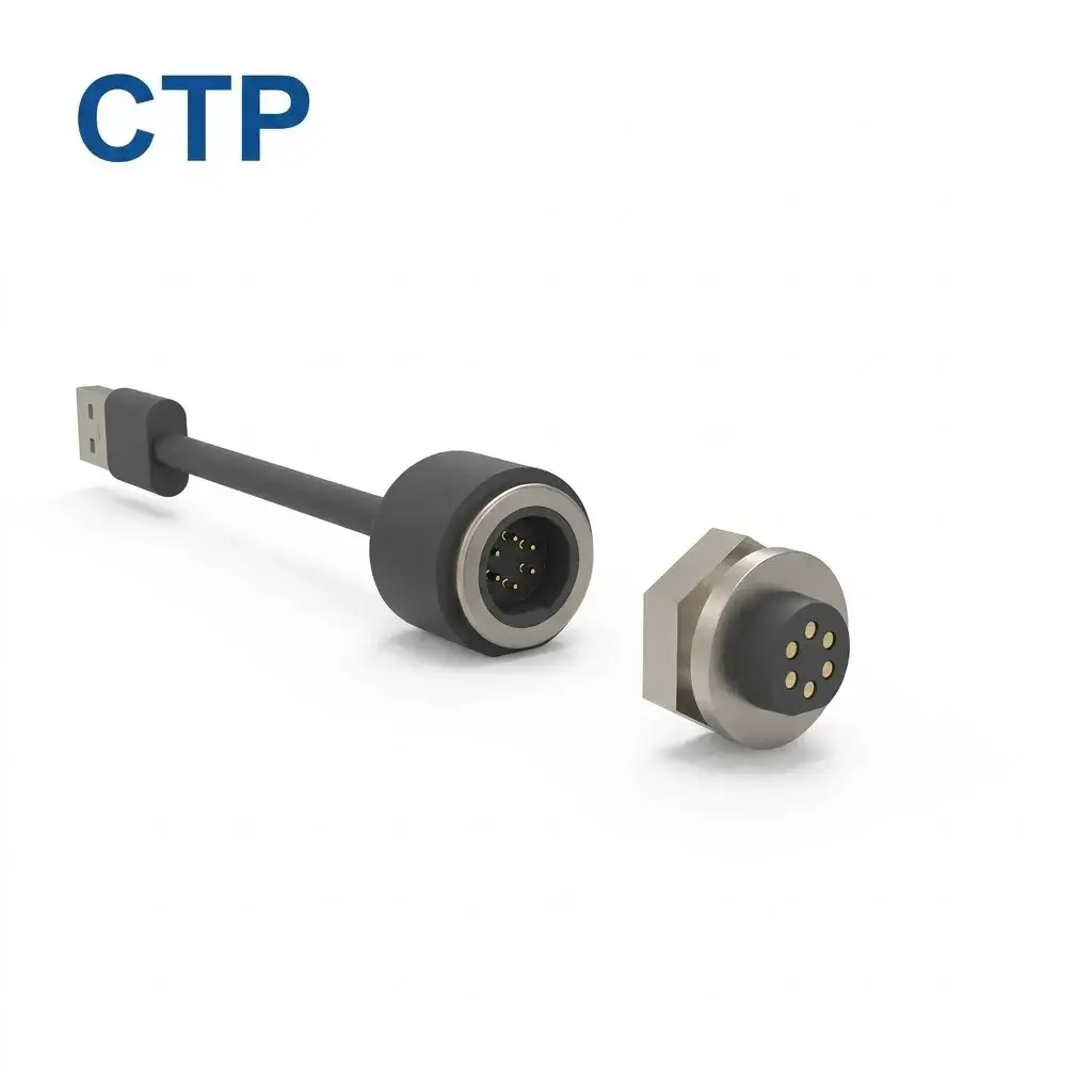
The CTP six-contact round magnetic cable, CTP-MCC-6P-RD-WP-A14, combines a circular cable-side interface with a separate device-side component. It gives the product team a different physical arrangement from the inline two-contact assembly.
The device-side measurement point should represent the intended installation
For a compact instrument, a reading taken at an exposed mating component may exclude a board joint that is present in the finished product. Decide whether the buying decision concerns the cable alone or the installed connection. Mark the relevant terminals and include the matching mate in the sample definition.
Six contact positions provide room for separately assigned functions, but they should not all be assumed to share charging current. Use the approved pin allocation. The cable construction, actual current capability and sealing requirements remain specific to the selected assembly.
Double-ended magnetic cable testing should identify both interfaces
A four-contact assembly connects two defined magnetic ends
Our four-contact double-ended magnetic cable, CTP-MCC-4P-DME-DATA-01, integrates two magnetic interfaces within one cable assembly. One molded end uses four spring-loaded contacts and the other provides the corresponding mating interface.
This can be a convenient product format where a detachable lead must connect two defined device positions. For voltage-drop comparison, identify which mating interfaces and counterpart parts are included. A result covering one end is different from one that includes the complete assembled route.
Imagine a desktop accessory linked to a removable control unit. The cable’s two ends can be developed with those locations, rather than adapted after the housings are finished. The test configuration should then reflect that same complete connection if it is the assembly being approved.
Wire-lead terminations make the board connection part of the discussion
The CTP five-contact cable with individual wire leads, CTP-MCC-5P-LIN-WL-01, combines a linear magnetic interface with separate leads for board, module or device integration. It gives an OEM more freedom over how the cable enters its own electrical assembly.
That freedom also means the final joint needs to be identified in the measurement plan. A cable tested before the leads are terminated is not the same specimen as the finished board assembly. Wire length, conductor choice and the included joints should stay visible in the sample record.
For an accessory manufacturer comparing a wire-ended cable with a finished molded lead, testing can clarify the trade-off. One route preserves flexibility in the customer’s assembly process; the other arrives with a more complete supplied termination. The useful comparison follows the actual items being purchased.
Keep voltage-drop testing connected to cable selection
CTP can develop the cable length, conductor arrangement, magnetic interfaces and opposite-end termination around the agreed device requirements. Our cable-selection article on voltage drop discusses the physical choices; this assessment then checks what reaches the device under the defined load.
Before approving a lead, ask which exact assembly the result represents. Keep its drawing, included mating parts, load condition and measurement points together. That makes a voltage-drop result useful for the product decision, rather than just another number in a cable comparison.